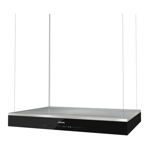
KaVo 5650 User manual

Operating instructions
Type 5650, 5651, 5652, 5653.
Always on the safe side.

KaVo Elektrotechnisches Werk GmbH
Wangener Straße 78
D-88299 Leutkirch
Tel.: 0 75 61 / 86-150 •Fax: 0 75 61 / 86-265

A 1 User information ............................................................................................................................................................2
A 1.1 Meaning of the pictograms ......................................................................................................................................2
A 1.2 Important information ..............................................................................................................................................2
A 1.3 Precautions ..............................................................................................................................................................2
A 2 Scope of delivery and accessories ..............................................................................................................................3
A 2.1 Scope of delivery ....................................................................................................................................................3
2.2 Accessories ................................................................................................................................................................3
A 3 Mains voltage - Mains frequency ..................................................................................................................................3
A 3.1 Identification plate ..................................................................................................................................................3
A 4 Location ..........................................................................................................................................................................4
A 5 Mounting and connection ..............................................................................................................................................5
A 6 Preparations for commencing operation ....................................................................................................................7
A 7 Control and functional elements ..................................................................................................................................8
A 8 Operation ........................................................................................................................................................................9
A 8.1Manual operation (continuous operation) without time preselection. ......................................................................9
A 8.2 Automatic operation by way of time preselection ..................................................................................................9
A 8.3 Manual operation while the preselected time is elapsing in "automatic operation". ............................................10
A 9 Maintenance ..................................................................................................................................................................11
A 10 Operating faults ............................................................................................................................................................12
A 11 Technical data ..............................................................................................................................................................13
Guarantee conditions ......................................................................................................................................................14
Declaration of conformity ................................................................................................................................................15
Spare parts ......................................................................................................................................................................16
Type 5650, 5651, 5652, 5653.
1

Type 5650, 5651, 5652, 5653.
2
A 1.2 Important information
The instructions for use should be
read by the user before starting up the
unit for the first time, in order to avoid
incorrect operation and other damage. If
other language versions are required, please
request these from your responsible KaVo
agent. Duplication and distribution of the
instructions for use (IU require KaVo's
prior consent.
All technical data, information and proper-
ties of the product described in the IU cor-
respond to the state on going to press.
Modifications and improvements to the
product as a result of new technical devel-
opments are possible.
This does not imply any right to retrofitting
of existing units.
KaVo assumes no responsibility for damage
arising through:
• external influences (poor quality of the
media or inadequate installation
• use of incorrect information
• improper use
• improperly performed repairs.
Repair and maintenance work - apart from
the activities described in these instructions
for use - may be performed only by quali-
fied technical personnel.
In the event of modifications by third par-
ties, the approvals become null and void.
KaVo recommends using only original
spare parts for operation and for repair.
A 1.3 Precautions
Safe operation and protection of the unit are
ensured only through proper use in accor-
dance with the instructions for use and
using the tools approved for the purpose.
The following should also be observed:
• the work safety regulations,
• the accident prevention regulations.
The extraction canopy can be installed
above preheating furnaces, polymerisation
units, waxing-out furnaces, boil-out units or
other equipment.
Intended use is possible only considering
the conditions in accordance
with EN 60335-1-2 and EN 61010.
The canopy cannot be used for the
extraction of explosive or aggressive
vapours, e.g. from acids.
The exhaust air must not be directed into a
chimney used for oven exhaust gases.
Ensure adequate ventilation of the room
containing the chimney. In the event of
simultaneous operation of extraction canopy
and fire grate, the negative pressure in the
same room must not be higher than 4 Pa.
(Fire grates VO Regulation of 31.01.86 and
DVGW-TRGI regulations 1986, official
gazette G 600 .
Compliance is required with official regula-
tions relating to discharges into the atmos-
phere.
A 1 User information
A 1.1 Meaning of the pictograms
Situations where failure to follow the
instructions may lead to danger,
damage to material or operating faults.
Important information for operator
and engineer.
Automatic mode
Automatic sequence
Close, screw in,
fasten, etc.
Open, release, loosen
+ more, higher
- less, lower
∞Continuous operation
Time, time sequence
Disconnect mains plug

Type 5650, 5651, 5652, 5653.
3
A 2 Scope of delivery and accessories
A 2.1 Scope of delivery
Checking the completeness of the unit.
Extraction canopy with fan unit
type 5650 consisting of:
1 Extraction canopy 1200/700
2 Filter elements
2 Brackets
1 Set of screws
Extraction canopy with fan unit
type 5651 consisting of:
1 Extraction canopy 1800/700
2 Filter elements
2 Brackets
1 Set of screws
Extraction canopy with fan unit
type 5652 consisting of:
1 Extraction canopy 1200/900
3 Filter elements
3 Brackets
2 Sets of screws
Extraction canopy with fan unit
type 5653 consisting of:
1 Extraction canopy 1800/900
3 Filter elements
3 Brackets
2 Sets of screws
A 2.2 Accessories
Optional accessory:
Pipe bend Mat .No. 0.659.0341
A 3 Mains voltage - Mains frequency
Electrical connection
Check that the local mains voltage and
mains frequency coincide with the specifi-
cations on the rating plate.
A 3.1 Identification plate
This provides information about
1the manufacturer
2the serial number
3GS mark
4CE mark
5Important: see accompanying
documents and safety information.
6the power consumption
7Ord. No. (REF
8the type of unit
1
”
3
4
6
7
8
5

Type 5650, 5651, 5652, 5653.
4
A 4 Location
The extraction canopy can be installed
above preheating furnaces, polymerisation
units, waxing-out furnaces, boil-out units or
other equipment.
The canopy cannot be used for the
extraction of explosive or aggressive
vapours, e.g. from acids.
The exhaust air must not be directed into a
chimney used for oven exhaust gases.
Ensure adequate ventilation of the room
containing the chimney. In the event of
simultaneous operation of extraction canopy
and fire grate, the negative pressure in the
same room must not be higher than 4 Pa.
(Fire grates VO Regulation of 31.01.86 and
DVGW-TRGI regulations 1986, official
gazette G 600 .
Compliance is required with official regula-
tions relating to discharges into the atmos-
phere.
It is important to obser e the minimum
room height.
Direct vertical connection requires a
minimum room height of 2500 mm;
connection via flanged pipe bend requires a
minimum room height of 2750 mm.
Provide appropriate exhaust-air ducting;
minimum pipe diameter 200 mm.
Note the size and weight of the unit prior to
its installation.
Dimensions with the control-unit:
Width: 1200 mm (1800 mm
Height: 400 mm
Depth: 790 mm (990 mm
Weight:
Typ 5650 = 46 kg
Typ 5651 = 60 kg
Typ 5652 = 52 kg
Typ 5653 = 69 kg

Type 5650, 5651, 5652, 5653.
5
A 5 Mounting and connection
Remove the filter elements and set of
screws (fitted to the compensation pan-
els or from the extraction canopy .
Mark on the wall the envisaged extraction
canopy´s upper edge of 2400 mm and its
width of 1200 mm or 1800 mm.
Align the brackets against the upper
edge line, and move them in at the left and
right by appprox. 50 mm. Mark elongated
holes on the wall.
For the 1800 mm extraction canopy a third
bracket must be fitted in the centre,
between the other two brackets.
Drill holes of ø 12 x 80 mm in the centre of
the marked elongated holes for the brackets
.
Mount the brackets on the wall with the
screws and align: the upper edge of the
bracket represents the upper edge of the
extraction canopy.
Screw set
is suitable only for rein-
forced concrete walls, masonry brick
and limestone.
Injection mesh anchors type F/M 10N
Mat. No. 0.224.6666 and hexagon bolts
M 10 x 20 DIN 933 Mat. No. 0.251.0202
must be used for vertical coring brick, per-
forated limestone, solid block of light
weight concrete (pumice , gas concrete and
cavity block of light concrete.

6
Type 5650, 5651, 5652, 5653.
Hang the extraction canopy onto the
brackets in the manner indicated by the
arrrow.
Link the connecting piece with the in-
house exhaust-air ducting system and seal.
The overall length of the exhaust-air
duct should be as short as possible to
achieve the highest extraction efficiency
rates. Bends and diminished duct diameters
must be avoided.
Panels and are interchangeable to
permit the most direct cable route to the
nearest socket.
To interchange the panels and , push
them upwards in arrow direction until they
can be swivelled down in arrow direction
and removed.
Install the filter elements (for the
extraction canopy 1200 mm = 2
and for 1800 mm = 3 filter elements .
First insert the filter element into the
top guide .
Swivel in the filter element , and push
downwards in arrow direction until its stop
point is reached.

7
Type 5650, 5651, 5652, 5653.
A 6 Preparations for commencing
operation
Plug the mains cable into an earthed
power socket that is correctly fused.
Press the start switch for the extraction fan
into OFF "0" position.
Press the mains switch into ON "I"
position.
Press the button "Set days of the week"
and set current day (1-7 using the adjuster
.
Press the button "Set time" and set the
current time with the adjuster .
Options!
Allow only qualified persons to carry out
installation and if necessary obtain the
required installation notes from KaVo
through dealers.
Connections are provided for external start
and stop actuations and can be operated by
switches or relays (d.c. or a.c. voltages
from 12V to 24V with the start switch
pressed in position OFF "0". The extraction
canopy can be started by closing a contact
(relay or applying a voltage.
Non-KaVo equipment (such as ventilators
can be started up during operation of the
extraction canopy via a relay (zero poten-
tial up to max. 6 A - 250 V.

Type 5650, 5651, 5652, 5653.
8
A 7 Control and functional ele-
ments
Extraction canopy
Brackets (2 or 3
Filter elements (2 or 3
Control-Unit
Panel with lead-through for cable
Panel
Fuse
100 V - 127 V, T 6.3 A delay-action
220 V - 240 V, T 3.15 A delay-action
Fan unit
Mains cable
Preselected time display
Time preselector
Program clear button (CL
3-speed extraction rate selector
Start switch for extraction fan
"1" Continuous operation
"0" Off
"2" Automatic operation
Mains switch
Set days of the week (1-7
Set time
Adjuster
Other manuals for 5650
1
This manual suits for next models
3
Table of contents
Other KaVo Ventilation Hood manuals