JVC XV-BP10J User manual

MODEL: XV-BP10J/XV-BP11J
SERVICE MANUAL
P/NO : AFN73271520 SEPTEMBER, 2009
MODEL: XV-BP10J/XV-BP11J
BLU-RAY DISC PLAYER

CONTENTS
SECTION 1 ........ SUMMARY
SECTION 2 ........ CABINET & MAIN CHASSIS
SECTION 3 ........ ELECTRICAL
SECTION 4 ........ HL-06P LOADER PART
SECTION 5 ........ REPLACEMENT PARTS LIST
1-1

SECTION 1
SUMMARY
CONTENTS
PRODUCT SAFETY SERVICING GUIDELINES FOR
BLU-RAY DISC PLAYER PRODUCTS ................................................................................................ 1-3
SERVICING PRECAUTIONS................................................................................................................... 1-4
• GENERAL SERVICING PRECAUTIONS
• INSULATION CHECKING PRODEDURE
• ELECTROSTATICALLY SENSITIVE (ES) DEVICES
SOFTWARE UPGRADE............................................................................................................................ 1-5
SPECIFICATIONS ....................................................................................................................................... 1-6
1-2

PRODUCT SAFETY SERVICING GUIDELINES
FOR BLU-RAY DISC PLAYER PRODUCTS
IMPORTANT SAFETY NOTICE
This manual was prepared for use only by properly trained audio-video service
technicians.
When servicing this product, under no circumstances should the original design be
modified or altered without permission from JVC. All components should be replaced
only with types identical to those in the original circuit and their physical location,
wiring and lead dress must conform to original layout upon completion of repairs.
Special components are also used to prevent x-radiation, shock and fire hazard.
These components are indicated by the letter “x” included in their component desig-
nators and are required to maintain safe performance. No deviations are allowed
without prior approval by JVC.
Circuit diagrams may occasionally differ from the actual circuit used. This way,
implementation of the latest safety and performance improvement changes into the
set is not delayed until the new service literature is printed.
CAUTION : Do not attempt to modify this product in any way. Never perform cus-
tomized installations without manufacturer’s approval. Unauthorized modifications
will not only void the warranty, but may lead to property damage or user injury.
Service work should be performed only after you are thoroughly familiar with these
safety checks and servicing guidelines.
GRAPHIC SYMBOLS
The exclamation point within an equilateral triangle is intended to alert
the service personnel to important safety information in the service
literature.
The lightning flash with arrowhead symbol within an equilateral trian-
gle is intended to alert the service personnel to the presence of non-
insulated “dangerous voltage” that may be of sufficient magnitude to
constitute a risk of electric shock.
The pictorial representation of a fuse and its rating within an equilat-
eral triangle is intended to convey to the service personnel the follow-
ing fuse replacement caution notice:
CAUTION : FOR CONTINUED PROTECTION AGAINST RISK OF
FIRE, REPLACE ALL FUSES WITH THE SAME TYPE AND
RATING AS MARKED NEAR EACH FUSE.
SERVICE INFORMATION
While servicing, use an isolation transformer for protection from AC line shock. After
the original service problem has been corrected, make a check of the following:
FIRE AND SHOCK HAZARD
1. Be sure that all components are positioned to avoid a possibility of adjacent
component shorts. This is especially important on items trans-ported to and from
the repair shop.
2. Verify that all protective devices such as insulators, barriers, covers, shields, strain
reliefs, power supply cords, and other hardware have been reinstalled per the
original design. Be sure that the safety purpose of the polarized line plug has not
been defeated.
3. Soldering must be inspected to discover possible cold solder joints, solder
splashes, or sharp solder points. Be certain to remove all loose foreign particles.
4. Check for physical evidence of damage or deterioration to parts and components,
for frayed leads or damaged insulation (including the AC cord), and replace if
necessary.
5. No lead or component should touch a high current device or a resistor rated at 1
watt or more. Lead tension around protruding metal surfaces must be avoided.
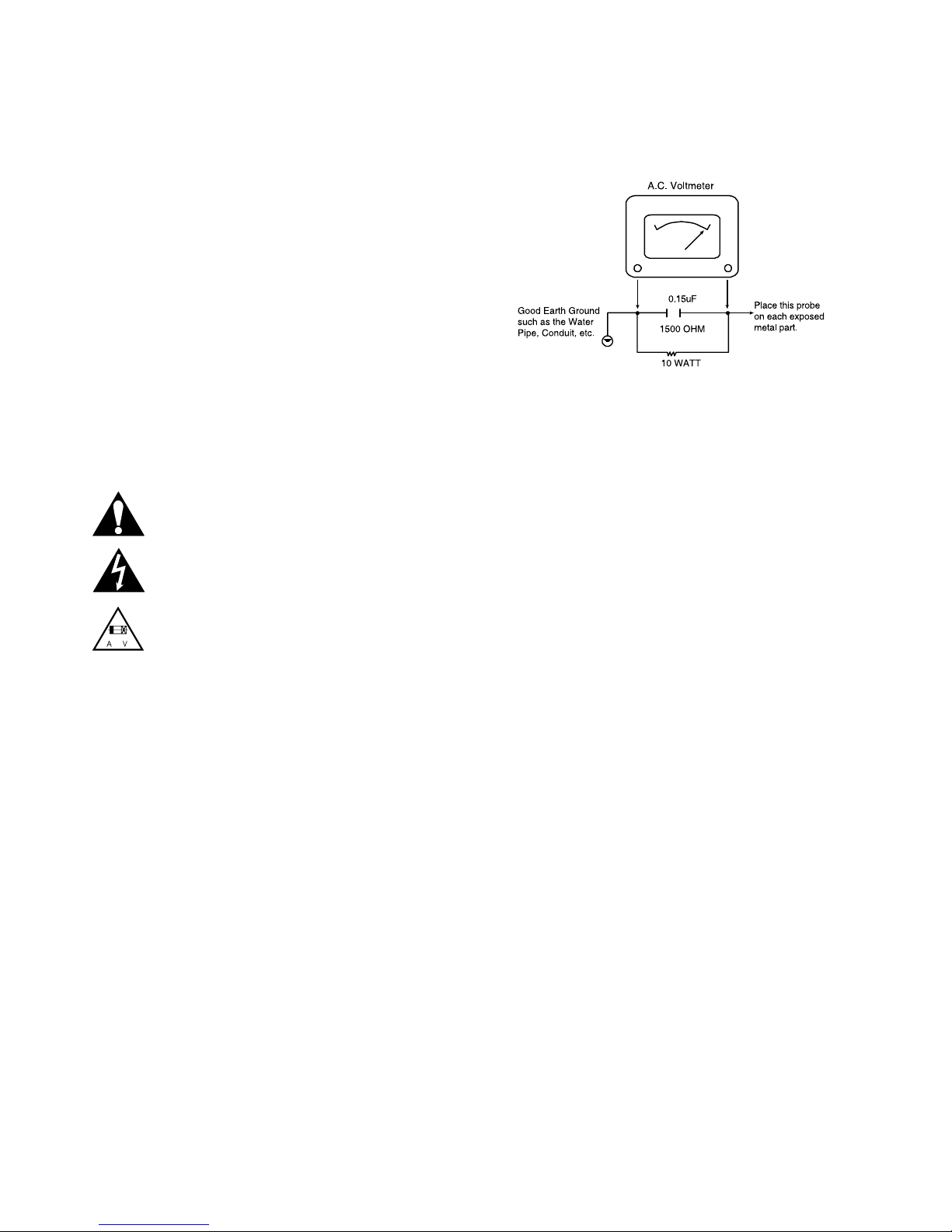
6. After reassembly of the set, always perform an AC leakage test on all exposed
metallic parts of the cabinet (the channel selector knobs, antenna terminals,
handle and screws) to be sure that set is safe to operate without danger of electri-
cal shock. DO NOT USE A LINE ISOLATION TRANSFORMER DURING THIS
TEST. Use an AC voltmeter having 5000 ohms per volt or more sensitivity in the
following manner: Connect a 1500 ohm, 10 watt resistor, paralleled by a .15 mfd
150V AC type capacitor between a known good earth ground water pipe, conduit,
etc.) and the exposed metallic parts, one at a time. Measure the AC voltage
across the combination of 1500 ohm resistor and .15 mfd capacitor. Reverse the
AC plug by using a non-polarized adaptor and repeat AC voltage measurements
for each exposed metallic part. Voltage measured must not exceed 0.75 volts
RMS. This corresponds to 0.5 milliamp AC. Any value exceeding this limit consti-
tutes a potential shock hazard and must be corrected immediately.
TIPS ON PROPER INSTALLATION
1. Never install any receiver in a closed-in recess, cubbyhole, or closely fitting shelf
space over, or close to, a heat duct, or in the path of heated air flow.
2. Avoid conditions of high humidity such as: outdoor patio installations where dew
is a factor, near steam radiators where steam leakage is a factor, etc.
3. Avoid placement where draperies may obstruct venting. The customer should
also avoid the use of decorative scarves or other coverings that might obstruct
ventilation.
4. Wall- and shelf-mounted installations using a commercial mounting kit must follow
the factory-approved mounting instructions. A product mounted to a shelf or
platform must retain its original feet (or the equivalent thickness in spacers) to
provide adequate air flow across the bottom. Bolts or screws used for fasteners
must not touch any parts or wiring. Perform leakage tests on customized installa-
tions.
5. Caution customers against mounting a product on a sloping shelf or in a tilted
position, unless the receiver is properly secured.
6. A product on a roll-about cart should be stable in its mounting to the cart.
Caution the customer on the hazards of trying to roll a cart with small casters
across thresholds or deep pile carpets.
7. Caution customers against using extension cords. Explain that a forest of exten-
sions, sprouting from a single outlet, can lead to disastrous consequences to
home and family.
1-3

SERVICING PRECAUTIONS
CAUTION: Before servicing the BLU-RAY DISC PLAYER
covered by this service data and its supplements and
addends, read and follow the SAFETY PRECAUTIONS.
NOTE: if unforeseen circumstances create conflict between
the following servicing precautions and any of the safety pre-
cautions in this publications, always follow the safety precau-
tions.
Remember Safety First :
General Servicing Precautions
1.Always unplug the BLU-RAY DISC PLAYER AC power
cord from the AC power source before:
(1) Removing or reinstalling any component, circuit board,
module, or any other assembly.
(2) Disconnecting or reconnecting any internal electrical
plug or other electrical connection.
(3) Connecting a test substitute in parallel with an electro-
lytic capacitor.
Caution : A wrong part substitution or incorrect polarity
installation of electrolytic capacitors may result in an
explosion hazard.
2.Do not spray chemicals on or near this BLU-RAY DISC
PLAYER or any of its assemblies.
3.Unless specified otherwise in this service data, clean elec-
trical contacts by applying an appropriate contact cleaning
solution to the contacts with a pipe cleaner, cotton-tipped
swab, or comparable soft applicator.
Unless specified otherwise in this service data, lubrication
of contacts is not required.
4.Do not defeat any plug/socket B+ voltage interlocks with
whitch instruments covered by this service manual might be
equipped.
5.Do not apply AC power to this BLU-RAY DISC PLAYER
and / or any of its electrical assemblies unless all solidstate
device heat sinks are correctly installed.
6.Always connect the test instrument ground lead to an
appropriate ground before connecting the test instrument
positive lead. Always remove the test instrument ground
lead last.
Insulation Checking Procedure
Disconnect the attachment plug from the AC outlet and turn
the power on. Connect an insulation resistance meter (500V)
to the blades of the attachment plug. The insulation resist-
ance between each blade of the attachment plug and acces-
sible conductive parts (Note 1) should be more than 1Mohm.
Note 1 : Accessible Conductive Parts include Metal panels,
Input terminals, Earphone jacks,etc.
Electrostatically Sensitive (ES) Devices
Some semiconductor (solid state) devices can be damaged
easily by static electricity. Such components commonly are
called Electrostatically Sensitive (ES) Devices. Examples of
typical ES devices are integrated circuits and some field effect
transistors and semiconductor chip components.
The following techniques should be used to help reduce the
incidence of component damage caused by static electricity.
1.Immediately before handling any semiconductor compo-
nent or semiconductor-equipped assembly, drain off any
electrostatic charge on your body by touching a known
earth ground. Alternatively, obtain and wear a commercially
available discharging wrist strap device, which should be
removed for potential shock reasons prior to applying
power to the unit under test.
2.After removing an electrical assembly equipped with ES
devices, place the assembly on a conductive surface such
as aluminum foil, to prevent electrostatic charge buildup or
exposure of the assembly.
3.Use only a grounded-tip soldering iron to solder or unsolder
ES devices.
4.Use only an anti-static solder removal device. Some solder
removal devices not classified as “anti-static” can generate
electrical charges sufficient to damage ES devices.
5.Do not use freon-propelled chemicals. These can generate
an electrical charge sufficient to damage ES devices.
6.Do not remove a replacement ES device from its protective
package until immediately before you are ready to install it.
(Most replacement ES devices are packaged with leads
electrically shorted together by conductive foam, aluminum
foil,or comparable conductive material).
7.Immediately before removing the protective material from
the leads of a replacement ES device, touch the protective
material to the chassis or circuit assembly into which the
device will be installed.
Caution: Be sure no power is applied to the chassis or cir-
cuit, and observe all other safety precautions.
8.Minimize bodily motions when handling unpackaged
replacement ES devices. (Normally harmless motion such
as the brushing together of your clothes fabric or the lifting
of your foot from a carpeted floor can generate static elec-
tricity sufficient to damage an ES device.)
1-4

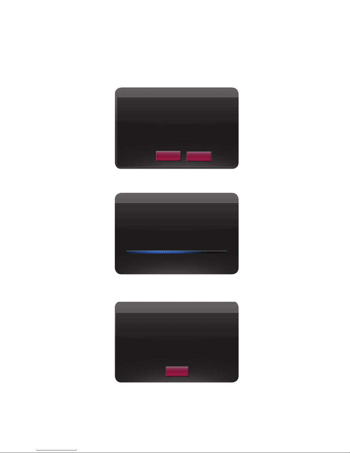
• Burn a DVD recordable disc or USB with a file that is named to “LG_BD_350BB.ROM”.
• Insert a upgrading disc or USB.
• Show help message for disc upgrade as follows.
< in the case of Back End program & Front End program >
Press play key to upgrade and it will show progress information
If the upgrade process is complete, the set will be rebooted with “Complete” message.
SOFTWARE UPGRADE
Do you want to update?
SW Version : BD.5.16.024
UPDATE
Model Name : BD320
Driver Version : H60700
SW Version : BD.5.16.025.B
OK Cancel
Updating……..
Model Name : BD320
Driver Version : H60700
SW Version : BD.5.16.025.B
Update is complete.
It will be automatically turned
off after 5 seconds.
UPDATE
Model Name : BD320
Driver Version : H60700
SW Version : BD.5.16.025.B
OK
1-5

SPECIFICATIONS
• GENERAL
Power requirements: AC 120V, 60Hz
Power consumption: 23W
Dimensions (W x H x D): Approx. 430 x 35 x 200 (mm)
Weight (Approx.): 3kg (6.6lbs)
Operating temperature: 41°F to 95°F (5°C to 35°C)
Operating humidity: 5% to 90%
• OUTPUTS
VIDEO OUT: 1.0V (p-p), 75Ω, sync negative, RCA jack x 1
ANALOG AUDIO OUT: 2.0Vrms (1kHz, 0dB), 600Ω, RCA jack (L, R) x 1
HDMI OUT (video/audio): 19pin (HDMI standard, Type A)
DIGITAL OUT (COAXIAL): 0.5V (p-p), 75Ω, RCA jack x 1
• SYSTEM
Laser: Semiconductor laser, wavelength: 405nm / 650nm
Signal system: Standard NTSC Color TV system
Frequency response: 20Hz to 20kHz
Signal-to-noise ratio: More than 100dB (ANALOG OUT connectors only)
Harmonic distortion: Less than 0.008%
Dynamic range: More than 95dB
Note : Design and specifications are subject to change prior notice.
1-6

SECTION 2
CABINET & MAIN CHASSIS
CONTENTS
EXPLODED VIEWS..................................................................................................................................... 2-2
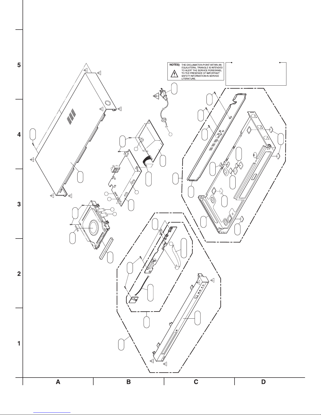
1. CABINET AND MAIN FRAME SECTION ................................................................................................. 2-2
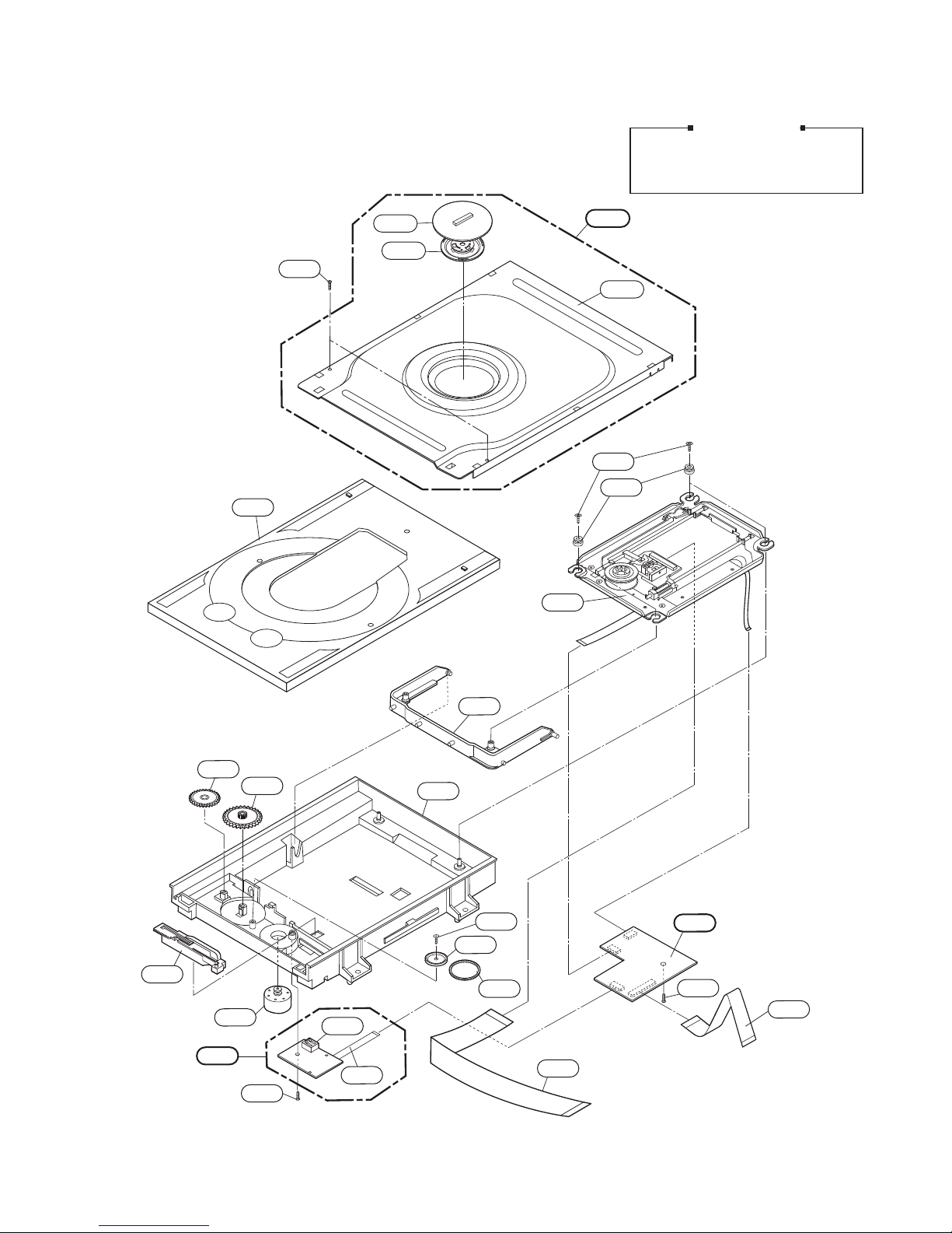
2. DECK MECHANISM SECTION (HL-06P) ................................................................................................ 2-3

3. PACKING ACCESSORY SECTION ......................................................................................................... 2-4
2-1

462
250
A
SPM
SDRAO
B
I
AMN
DR
AOB
CB
D
468
P101
A
300
468
CB
320
261B
261A
261C
465 465
260
261
261
261
TIMER
BOARD
KEY
BOARD
D
CABLE1
275
452
CN904
283
A43
A50
A46
A44
A47
SVC purchase order caution
Key board is array coming timer board.
Purchase order board separately supply
incomprehensible.
Supply is possible in Location No. A50
state in exploded views.
262
A43A
EXPLODED VIEWS
1. CABINET AND MAIN FRAME SECTION
2-2
465

2. DECK MECHANISM SECTION (HL-06P)
1001
1003
1002
A001
1439
1437
1049
1026
1011
1013
1012
1045
1439
1016
1015
A006
1018
A005 1030
1020
1031
1439
1433
1043
1017
1025
Refer to "HOW TO USE THE SA
RESET FUNCTION" (Page4-6 ~ 4-7)
after replacing 1049.
Service Notice
2-3
This manual suits for next models
1
Table of contents
Other JVC Blu-ray Player manuals

JVC
JVC XV-BP1C User manual

JVC
JVC 1010MTH-SW-MT User manual

JVC
JVC LVT2101-001A User manual

JVC
JVC SRC-1020-1ORT User manual

JVC
JVC XV-BP1UB User manual

JVC
JVC SR-HD1250US - Blu-ray Disc & Hdd Recorder User manual

JVC
JVC SR-HD1700US Installation guide

JVC
JVC XV-N680B Manual

JVC
JVC SR-HD2500US User manual

JVC
JVC SR-HD1250US - Blu-ray Disc & Hdd Recorder User manual