JUKI HZL-UX8 User manual

SERVICE MANUAL
HZL-UX8 Series
COMPUTER SEWING MACHINE

Be sure to observe the following to protect against a re, electrical shock, injury or damaged components.
* Be sure to unplug the machine before disassembly, assembly or adjustment of the machine.
* Be sure to carefully prevent electric cords from being caught, coated surfaces from being damaged
as well as wrong wiring during assembly.
* Be sure to use the proper genuine parts when changing any of the machine parts.
CAUTION:
CONTENTS
[1] Specications of HZL-UX8 ........................................................................................ 1
[2] Search by trouble (related to mechanical components) ........................................ 3
[3] Principal parts ............................................................................................................ 4
[4] Disassembling the machine covers ......................................................................... 5
[5] PCB connection diagram ........................................................................................ 12
[6] Adjustment ............................................................................................................... 16
6-1 Adjusting the needle bar height ...................................................................... 16
6-2 Adjusting the needle entry point ..................................................................... 17
6-3 Feed dog height ................................................................................................ 18
6-4 Timing belt ........................................................................................................ 19
6-5 Feed timing ....................................................................................................... 19
6-6 Adjusting the shield ......................................................................................... 20
6-7
Hook driving shaft coupling and the lateral timing of the hook driving shaft
.. 21
6-8 Timing between the needle and the hook ...................................................... 22
6-9 Clearance between the needle and the blade point of hook ........................ 23
6-10 Position of the hook rotation stopper plate ................................................. 25
6-11 Adjusting the bobbin thread tension ............................................................ 25
6-12 Adjusting the needle thread tension ............................................................. 26
6-13 Vertical position of the needle threading hook ............................................ 27
6-14 Adjusting the auxiliary hook height .............................................................. 28
6-15 Adjusting the opening amount of auxiliary hook ........................................ 29
6-16 Adjusting the presser bar height .................................................................. 29
6-17 Motor belt ........................................................................................................ 30
6-18 Longitudinal feed ............................................................................................ 31
6-19 Presser foot lifting .......................................................................................... 32
6-19-1 Position of the presser foot lifting motor ....................................................32
6-19-2 Adjusting the height of the auto-lifter ..........................................................33
6-20 Thread trimming ............................................................................................. 34
6-20-1 Attaching/removing the thread trimmer unit ...............................................34
6-20-2 Adjusting the thread trimming switch .........................................................35
6-21 Attaching/removing the top feed dog ........................................................... 36
6-22 Position of the automatic DF motor .............................................................. 37
6-23 Bobbin thread detection sensor ................................................................... 38
6-23-1 Attaching/removing the bobbin thread detection sensor ..........................38
6-23-2 Adjusting the bobbin thread detection sensor ...........................................39
6-24 Service mode .................................................................................................. 40
6-24-1 Service mode screen .....................................................................................40
6-24-2 Service-mode items and descriptions .........................................................40

– 1 –
(1) Power switch
• 220-240V AC common to 50/60 Hz
• 120V AC common to 60 Hz
(2) Power consumption
• 90 W
(3) Dimensions and weight
• Dimensions Main unit: 602 (width) × 264 (depth) × 310 (height) (mm)
• Weight Main unit: 14.9 kg
(4) Revolution control
• Slide style speed control
Straight stitch 80 to 1,050 sti/min (SPM)
Pattern stitch 80 to 750 sti/min (SPM)
Reverse stitch 80 to 1,050 sti/min (SPM)
(Sewingspeedotherthanthespeciedrangecanbesetoptionally.)
80 to 1,050 sti/min (SPM) (when the speed controller is used.)
Bobbinwinding 1,500to3,000sti/min(SPM)
Low-speed start 80 to 110 sti/min (SPM) (approx. 1 second only when the power switch is turned ON.)
• Foot controller
Evenwhenthefootcontrollerisused,thespeedcontrolfunctionbymeansoftheslideriseective.
Tostopthemachine,eitherreleasethefootcontrollerorpressstart/stopbutton.
Thenumberofrevolutionsiscontrolledinthewaysamewiththecaseoftheslidespeedcontrol.
Toe-uppedalingfunctioncanbesetoptionally.
• Safety control
When the motor shaft of the sewing machine is accidentally constrained, the power supply to the motor is
stopped within two seconds.
Whenthemotorisoverheated,thebuiltinthermalswitchstopsthepowertothemotor.
Notethatthemachinecanberestartedoncethemotorspontaneouslycoolsdown.
(5) Stop position
•Uponnishingsewing,themachinestopsaccordingtothepresetneedlestopposition(withitsneedleupor
down).
•Uponnishingreversestitching,themachinestopswithitsneedledown.
• Needle moves down when the machine has preset so that the needle stops at its up position and needle up/
downbuttonispressed.
• Needle moves up when the machine has preset so that the needle stops at its down position and needle up/
downbuttonispressed.
• In the case of fault, the machine stops immediately (stop position varies).
(6) Zigzag width
• Max. 7 mm depending on the pattern selected
(7) Amount of feed
•Theamountoffeedischangedinincrementsof0.2mmbythestitchlengthadjustingdial(orbutton).
(Fortheparallelpartsofabuttonholeandsatinstitches,theamountfeedischangedinincrementsof0.1mm.)
Default setting: 2.4 mm (for straight stitching)
[1] Specications of HZL-UX8

– 2 –
(8) Pattern selection
• Selection is made on the touch panel
(9) Number of patterns that can be selected
• Max. 70 patterns
(10) Number of patterns
• 368
(11) Automatic threading device
•Thehooksectionmakesaturnbyloweringthethreadinglever,andautomaticallyreturnstoitsoriginalposition
after completion of threading.
(12) Automatic lock stitch
WhenthebacktackingswitchisturnedON:
• Straight stitch: Three stitches are sewn in normal direction and three stitches are sewn in reverse direction at
thebeginningandend(thereverseswitchisturnedON)ofsewing.
Amount of feed: Same with the preset amount of feed
• Other patterns: Zero-feed is inserted and one each stitch is sewn in the normal and reverse directions at the
beginningandend(thereverseswitchisturnedON)ofsewing.
Amount of feed: Fixed at 0.4 mm
(13) Buttonholing
Auto-returntypefullautomaticbuttonholing
Buttonholing size detection
(14) Save and call patterns
Selectedpatternsandpatternsettingscanbestoredinmemory.
Inaddition,thepatterncanbecalledupfrommemoryforsewing.
Numberofpatternsthatcanbestoredinmemory:10(folders)
(15) Helpful messages
• Presser foot lifting lever
• Buttonholing foot
• Display of pattern storage limitation
• Pattern clear prompt
• Memory storage
• Acceptance of setting change
• 2-needle setting
• Motor lock
• Straight stitch selection
•Throatplatehascomeo
• Top feed
– 3 –
[2] Search by trouble (related to mechanical components)
Phenomenon Itemtobechecked
Faulty thread tension 6-10: Position of the hook rotation stopper plate
6-11:Adjustingthebobbinthreadtension
6-12:Adjustingtheneedlethreadtension
Stitch skipping 6-1:Adjustingtheneedlebarheight
6-2:Adjustingtheneedleentrypoint
6-5: Feed timing
6-8:Timingbetweentheneedleandthehook
6-9:Clearancebetweentheneedleandthebladepointofhook
Threadbreakage 6-1:Adjustingtheneedlebarheight
6-8:Timingbetweentheneedleandthehook
6-10: Position of the hook rotation stopper plate
Hitch stitch 6-2:Adjustingtheneedleentrypoint
Faulty material feed 6-3: Feed dog height
6-16:Adjustingthepresserbarheight
6-22: Position of the automatic DF motor
Contactbetweenneedleandthroatplate
or hook
6-2:Adjustingtheneedleentrypoint
6-5: Feed timing
6-8:Timingbetweentheneedleandthehook
Faulty pattern shape 6-3: Feed dog height
6-18: Longitudinal feed
Faulty automatic thread trimming 6-6:Adjustingtheshield
6-20-1: Attaching/removing the thread trimmer unit
6-20-2:Adjustingthethreadtrimmingswitch
Faulty operating noise 6-4:Timingbelt
6-17:Motorbelt
Needle threader 6-13: Vertical position of the needle threading hook
Fails to start sewing 6-19-2:Adjustingtheheightoftheauto-lifter
Faulty automatic presser foot lifting height 6-19-2:Adjustingtheheightoftheauto-lifter
– 4 –
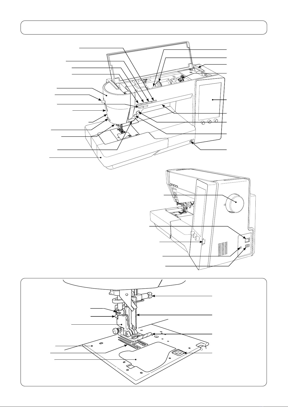
[3] Principal parts
Spool cap (large)
Spool pin
Operation panel
Face plate cover
Threading lever
Start/stopbutton
Presser foot lifting lever
Needle setscrew
Needle
Presser foot
Sensorpinholeforbuttonholing
Presserfootreleasingbutton
Feed dog
Throat plate
Hook cover
Bobbinwinding
shaft
Hookcoverreleasebut-
ton
Presser foot holder
Threadtrimmingbutton
Auxiliarybed
(accessory case)
Thread cutter
Lockstitchbutton
Speed controller
Needleup/downbutton
Knee lifting lever
hole
Light under arm
Reverse stitch
button
Feed dog UP/DOWN /
LOCKMODEbutton
Hand wheel (pulley)
Power switch
Machine-socket-inlet
Foot-controller-jack
USB insertion slot
“JUKI Smart Feed”
Presser foot holder setscrew
Presserfootautoliftbutton
Handle

– 5 –
❶❶❷❷
○Toremovethetopcover,bowthehingesectionoftherightsideofthecover.
○Remove setscrews ❶and ❷from the face cover.
Then, remove the face cover.
○Fittingaat-bladescrewdriver(T-shape)inthenearestslotinthethroatplate,
pushupthethroatplatewiththescrewdriveruntilitcomeso.
Then remove the throat plate.
[4] Disassembling the machine covers
1) Top cover
2) Face cover
3) Throat plate
T-shape
– 6 –
Base tension
❺❺❻❻
❼❼
❽❽
❸❸
❹❹
❾❾
Junction connector
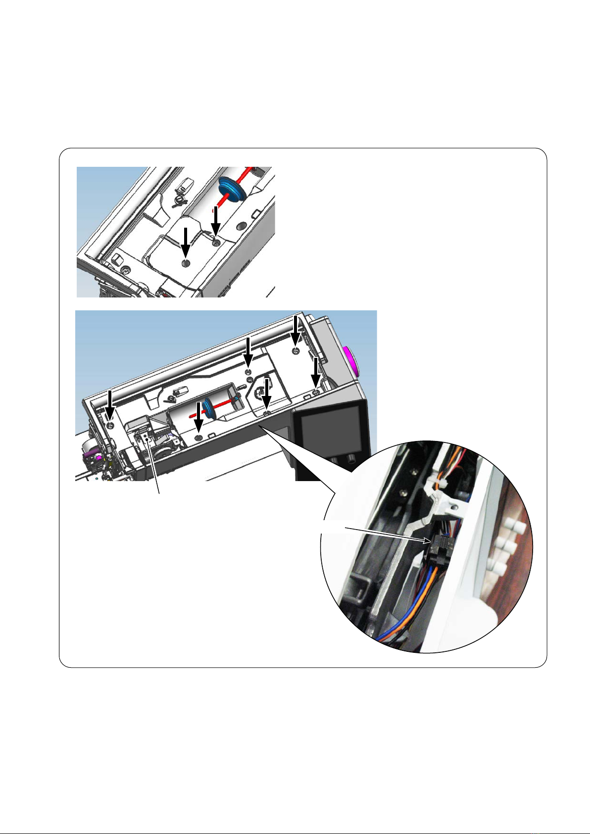
○Remove setscrews ❸and ❹from the thread tension cover.
Remove the thread tension cover.
○Remove setscrews ❺to from the spool cover.
○Removethebobbinwindingmotorjunctioncablefromthejunctionconnector.
○Remove the spool cover from the main unit of the machine, paying attention to
thebasetension.
4) Spool cover
– 7 –
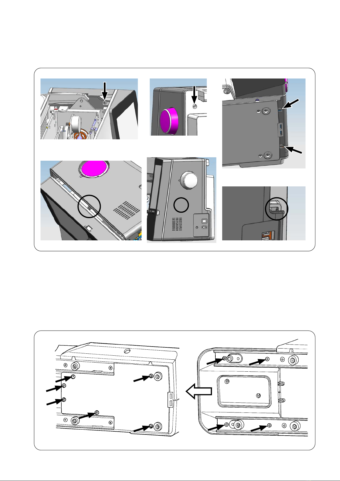
○Remove setscrews to ofthebottomcoverB(onthehandwheelside)to
detachthebottomcoverB.
○Remove setscrews to ofthebottomcoverA(ontheframeside).Draw
outthebottomcoverAinthedirectionofthearrowwhilepushingupthetipof
the cover.
6) Bottom cover
○Removebeltcoversetscrewsto .
○Push portion Bto disengage portion A.
○DetachthebeltcoverwhilecarefullycheckingthesupportofportionC.
5) Belt cover
A
B
C
– 8 –
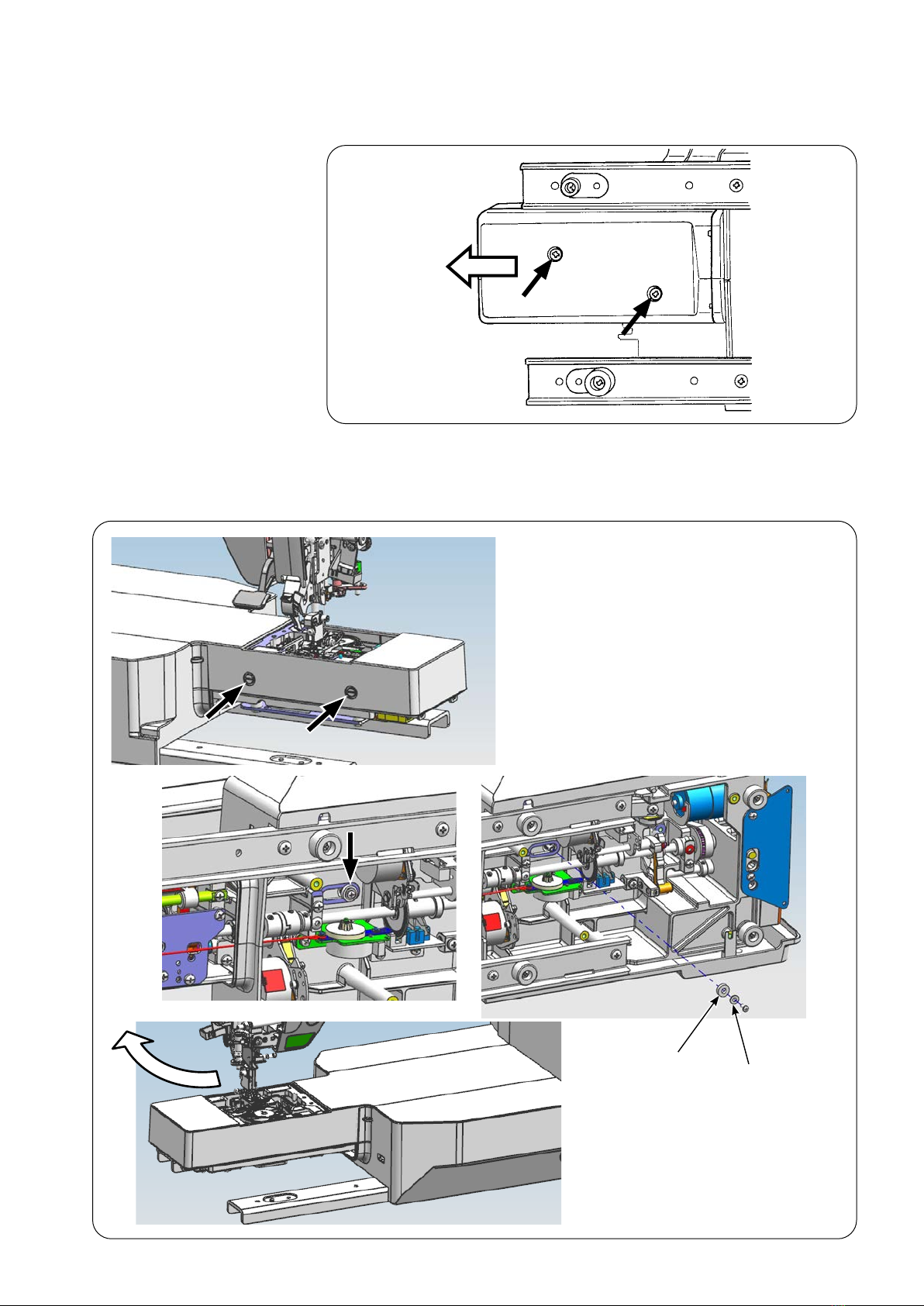
○Removefree-armlowerbottomcoversetscrewsand .Pulloutthebot-
tom cover of the free arm in the direction of the arrow.
7) Bottom cover of the
free arm
8) Upper cover of the
free arm
○Remove free-arm upper cover setscrews and . Remove setscrew ,
the collar and the washer, and pull out the free-arm upper cover in the direc-
tion of the arrow.
Collar
Washer
Other manuals for HZL-UX8
1
Table of contents
Other JUKI Sewing Machine manuals