
JTS CS-1 User manual


1. Important Cautions
2. Features
3. Specication
3.1 Control and power supply unit (CU)
3.2 Delegate and Chairman unit
4. Preparing Procedure
4.1 Connecting between the delegate and chairman units
4.2 Connecting up to 150 unit
4.3 Connecting an external microphone
4.4 Connecting a wireless microphone
4.5 Recording | Playing back the discussion
4.6 Connecting a PA-system | other external equipment
4.7 Connecting a telephone coupler
4.8 Connecting Equalizer or other effects
4.9 Connecting power cord
5. Operation
5.1 System testing
5.2 Date / time setting
5.3 Key Lock
5.4 Counter operation
5.5 Delegate unit operation
5.6 Chairman unit operation
5.7 Volume control of the delegate and chairman units
5.8 Volume control of headphone and internal speaker of CU
5.9 Using a headphone
5.10 Open mode
5.11 Time mode
5.12 Override mode
5.13 Chairman only mode
6. Technical Data
6.1 Electrical and Electro-Acoustical Characteristics
6.2 Mechanical Specications
6.3 General Specications
6.4 Pin conguration
2
4
6
6
7
7
8
8
9
9
10
11
11
11
12
12
13
13
14
14
15
15
16
16
17
18
18
19

1
1.Important Cautions
• Make all connections before plugging the unit into an AC
power outlet.
• Do not leave the devices in a place with high temperature
or high humility.
• Do not handle the power cord with wet hands.
• Keep the devices away from re and heat sources.
• Hot swapping is forbidden.
2. Features
The innovative CS-1 i-Conference Discussion System is
equipped with JTS in-house made ECM capsule, intelligent
automatic mixing technology and integrated acoustic and
mechanical design, providing Turn-Key solution and deliv-
ering consistently natural, feedback-free audio performance
with any environment.
The i-Conference Discussion System is ideal for discussion
and meeting with up-to 150 attendants.
A CS-1 i-Conference Discussion System consists of:
• One Control and power supply unit (CU)
• Maximum 50 delegate or chairman units
• Peripheral audio and/or telecommunication equipment.
The CU is the center of the discussion system which con-
trols the microphones of the chairman and delegate units
as well as connects to other audio input and output. It also
supplies the power for the CU itself, and up to 50 chairman
and delegate units.
The delegate unit enables the attendants to participate in a
discussion by speaking through a microphone, controlled by
a microphone ON/OFF push-button, and listening discus-
sion by the internal loudspeaker and external headphone.
The chairman unit not only provides the same function as
the delegate unit, but also supports the addition of a “Prior-
ity button”,that enables the chairman to control the discus-
sion by temporary or permanently overriding and deactivat-
ing all active microphones
of the delegate units.

2
3. Specication
3.1 Control and power supply unit (CU)
3.1.1 Front Panel
1) Power On/Off switch
2) LCD display: setting and displaying mode status, simul-
taneously maximum user number, and date.
3) Set button: pressing “set” button to enter setting mode on
the LCD panel.
4) Up & Down buttons: pressing “Up” or “Down” to switch
the setting.
5) Speaker Volume control: controlling all connected chair-
man and delegate units.
6) Monitor Volume control: controlling both speaker and
headphone of the CU.
7) Headphone input: allowing another alternative of
listening discussion. While inserting the headphone, the
loudspeaker will be deactivated.
8) Loudspeaker.

3
3.1.2 Rear Panel
1) DCV input:
2) Insertion input and output switch: default setting is
“In”, when switching to“In”, all internal speaker will be
muted, and switch to external audio device.
3) Telephone coupler input and output:
4) Insertion input and output: connect to an external audio
equalizer for speech quality improvement.
5) Recorder input and output: connect to a recorder that-
could record and play back the discussion.
6) Line input and output: connect to PA-System or other
audio devices.
7) Gain control 1: control the volume level of Recording
input.
8) Gain control 2: control the volume level of Microphone
XLR input.
9) Trunk output 1 and 2: connect to chairman and delegate
units. *
10) Microphone XLR input: connect to external micr phone
or wireless microphone receiver.
* Note: Hot swapping is forbidden.

4
3.1.3 LCD Display
1) Mode status: show the discussion mode
2) Simultaneously user number: the maximum number of
simultaneously active users is four.
3) Date | Set: While setting, “Set” will ash.
4) Time:
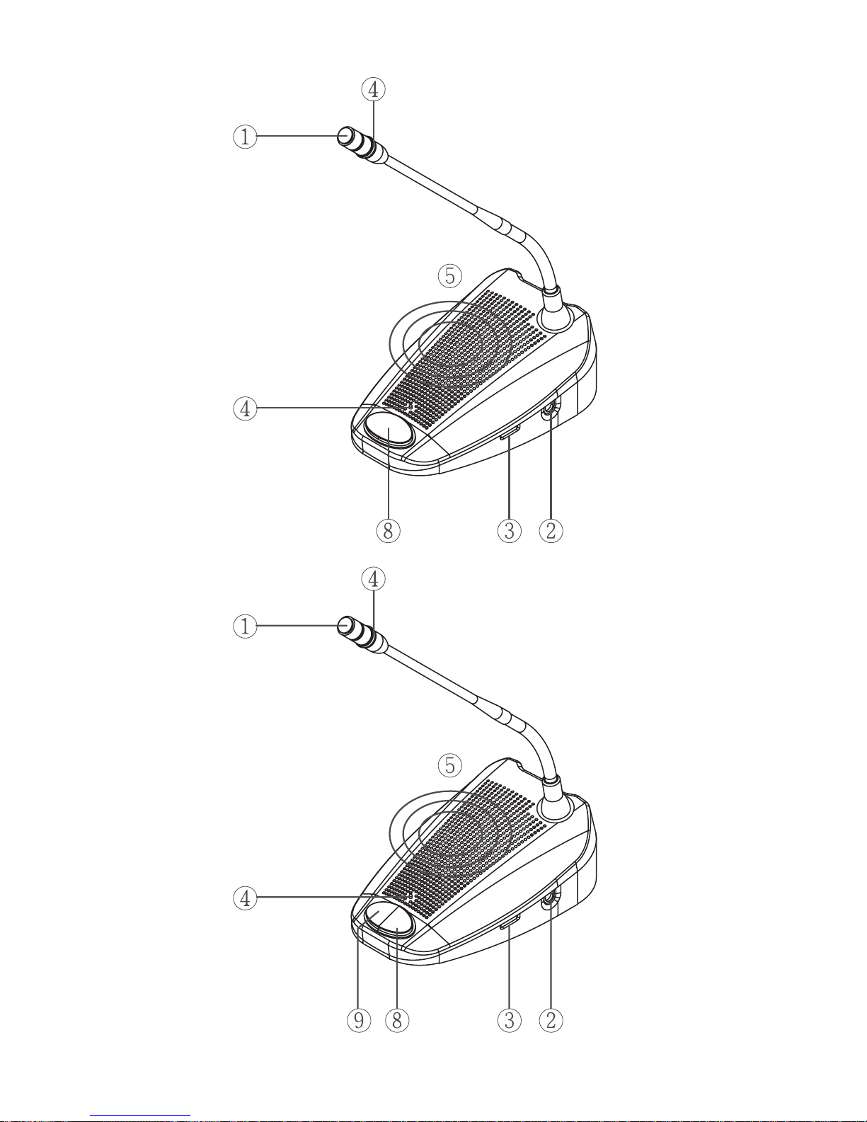
3.2 Delegate and Chairman unit
1) Gooseneck Microphone
2) Two 3.5mm stereo headphone sockets
3) Rotary volume control: control the volume level of the
headphone.
4) Ring & Microphone “On” indicator: While microphone
is activated, both indicators will light up.
5) Loudspeaker
6) 7-pole circular female socket *
7) 7 pole circular male connection cable
8) Microphone ON/OFF push-button
9) Chairman Priority button
10) Priority button setting switch: The default setting
is“A”, meaning when releasing the priority button, the
microphone on delegate units will be re-activated. When
switching to “B”, the microphone on delegate units
won’t be reactivated after the priority button is released.
11) Gooseneck Microphone Gain Control: Control the vol-
ume of the microphones on the chairman and delegate
units.
* Note: Hot swapping is forbidden.
A
B
5
Delegate
Chairman unit

6
4. Preparing Procedure
4.1 Connecting between the delegate and
chairman units
1) Insert 7-pole circular male connection cable of the chair-
man or delegate units into the Trunk socket on the CU.
2) Connect the second unit to 7-pole circular female socket
of the rst unit.
3) Repeat the above actions for the rest of units. (Maximum
connected number per trunk socket is 25)
4.2 Connecting up to 150 units
The i-Conference discussion system can be used with up to
150 units by adding maximum 2 additional CUs functioning
as power supply units only. The system is controlled by the
master CS-1 CU. The cables necessary for these connections
can be delivered by your local dealer.
3...253...25

7
4.3 Connecting an external microphone
1) Put the external microphone connector into the micro-
phone XLR input of the CU.
2) Adjust the sensitivity by using the gain control 2.
Caution:
Always use the microphone with balanced output.
The microphone XLR input provides a 12V phantom power
supply.
4.4 Connecting a wireless microphone
1) Connect a wireless receiver to the microphone XLR
input of CU.
2) Adjust the sensitivity by using the gain control 1
Table of contents
Other JTS Conference System manuals


Popular Conference System manuals by other brands

Kramer
Kramer VIA GO quick start guide

AVT
AVT MAGIC AC1 Go Configuration guide

ProSoft Technology
ProSoft Technology AN-X4-AB-DHRIO user manual

Sony
Sony PCS-I150 Operation guide

Middle Atlantic Products
Middle Atlantic Products VTC Series instruction sheet

Prentke Romich Company
Prentke Romich Company Vanguard Plus Setting up and using


