
Johnson Controls S300 Series Assembly instructions

December 2017
24-10239-359 Revision C
S300
Series
S300-DIN-S
Hardware Installation Manual

Copyright 2017
Johnson Controls
All Rights Reserved
No part of this document may be reproduced without the prior permission of Johnson Controls.
If this document is translated from the original English version by Johnson Controls, all reasonable endeavors will be
used to ensure the accuracy of translation. Johnson Controls shall not be liable for any translation errors contained
herein or for incidental or consequential damages in connection with the furnishing or use of this translated material.
Due to continuous development of our products, the information in this document is subject to change without notice.
Johnson Controls shall not be liable for errors contained herein or for incidental or consequential damages in
connection with furnishing or use of this material. Contents of this publication may be preliminary and/or may be
changed at any time without any obligation to notify anyone of such revision or change, and shall not be regarded as
a warranty.
Other Manufacturers’ Documentation
Johnson Controls does not duplicate documentation of other equipment manufacturers. When necessary, Johnson
Controls provides documentation that supplements that of other manufacturers. When unpacking equipment, keep all
original manufacturer documentation for future reference.
Technical Support
For factory technical support, Johnson Controls authorized field technicians or authorized dealer representatives can
contact Global Security Solutions Technical Support by phone at (866) 893-0423 or (414) 524-1214, or by email at
support.globalsecurit[email protected]. They can also call the Field Support Center at (800) 524-1330 or (414)
524-5000 and use options 6, 1, 7.
End users and customers should contact their local Johnson Controls branch or authorized dealer for any of their
support needs (technical support, maintenance contracts, on-site field support, P2000 Software Service Agreements,
Service Partnerships, and so on). Visit http://www.johnsoncontrols.com/location-finder to find your local Johnson
Controls office.
For material returns contact the branch if the material was purchased through a Johnson Controls branch or through
the Product Sales Operations Team, if ordered through the Advanced Order Management System (AOMS) and follow
the RMA process; or contact the authorized dealer representative where the material was purchased directly.
Acknowledgments
Metasys® and Johnson Controls® are trademarks of Johnson Controls. All other company and product names are
trademarks or registered trademarks of their respective owners.

Declaration of Conformity
United States: This equipment, S300-DIN-S, has been tested and found to comply with the limits for a Class B
digital device, pursuant to Part 15 of the FCC rules. These limits are designed to provide reasonable protection
against harmful interference in a residential installation. This equipment generates, uses and can radiate radio
frequency energy and, if not installed and used in accordance with the instructions, may cause harmful interference to
radio communications. However, there is no guarantee that interference will not occur in a particular installation. If
this equipment does cause harmful interference to radio or television reception, which can be determined by turning
the equipment off and on, the user is encouraged to try to correct the interference by one or more of the following
measures:
Reorient or relocate the receiving antenna.
Increase the separation between the equipment and receiver.
Connect the equipment into an outlet on a circuit different from that to which the receiver is connected.
Consult the dealer or an experienced radio/TV technician for help.
The user is cautioned that changes and modifications made to the equipment without approval of the manufacturer
could void the user's authority to operate this equipment.
Canada: CAN ICES-3 (B)/NMB-3(B)

UNDERWRITERS LABORATORIES COMPLIANCE VERIFICATION SHEET
The following model number is listed under Underwriters Laboratories® (UL) 1076 for Proprietary Burglar Alarm
Units and Systems, UL 294 for Access Control Systems Units, and Underwriters Laboratories of Canada
ULC/ORD-C1076-86.
S300-DIN-S
When installed at the site the following requirements must be met to comply with these standards.
1. The S300-DIN-S is intended to be used with listed sub-assemblies found in file BP4166, Vol. 2, Sec. 7.
2. The S300-DIN-S in combination with the listed sub-assembly must be connected to a UL Listed
Uninterruptible Power Supply that provides a minimum of 24 hours of AC emergency power.
3. The tamper switch must be connected to a listed sub-assembly and enabled at all times.
4. Transient protection devices that are installed must not be removed or defeated.
5. Do not connect equipment to an AC power source that is controlled by a switch.
6. Model S300-DIN-S must use a Class 2 direct plug-in transformer rated 120 VAC input and 24 VAC, 50 VA
output from one of the following manufacturers:
Basler, part number BE116450CAA or BE116450AAA
Potter Electric Signal Co. (Amseco), model XR-2450LED
Revere Industries, model RT-2450SL/M
7. Model S300-DIN-S power supply must have the voltage selection jumper set to 24VDC.
8. UL 294 Performance Levels
Destructive Attack Level I
Endurance Level IV
Line Security Level I
Standby Power Level II

24-10239-359 Rev. C 1
This document contains confidential and proprietary information of Johnson Controls
© 2017 Johnson Controls
HARDWARE INSTALLATION
INTRODUCTION
This document provides information necessary for the installation of the S300-DIN-S
enclosure and related equipment, including field devices.
The S300-DIN-S is a small enclosure used to house a DIN-mountable electronic device and,
optionally, a backup battery unit.
Field device Power supplyBackplate
Backup batteries Tamper switchGround strap DIN rail
The S300-DIN-S comes with a backplate, a tamper switch, a lock, and a ground strap kit.
The backplate contains a power supply and a DIN rail for device mounting.
The figure below gives you an overview of the small enclosure with all components
installed. The device shown here is the S300-DIN-RDR2S.
APPLICATION
One device can be mounted on the DIN rail (for example, a S300-DIN-RDR2S module,
a CK722 controller, or a CK721-A controller).
You can also mount a backup battery unit. The unit is composed of two 12V lead-acid
batteries in one battery bracket.

Hardware Installation S300-DIN-S
2 24-10239-359 Rev. C
This document contains confidential and proprietary information of Johnson Controls
© 2017 Johnson Controls
INSTALLATION
This section describes the hardware installation of the S300-DIN-S enclosure and its
components.
Unpacking the Equipment
Carefully inspect the shipping containers as soon as you receive them (with the
delivery agent present). Some shipping companies want to have an agent present
when a damaged container is opened. If a container is damaged, open it
immediately, inspect the contents, and have the agent make note on the shipping
document. Check the purchase order against the packing slips to ensure the order is
complete. If the contents of a container are damaged in any way, notify the carrier
and your Johnson Controls representative immediately. Report any discrepancies to
your Johnson Controls representative. Save the packing materials for possible return
shipments.
Package Contents
Backplate
Tamper switch
Lock
Ground strap kit
This document
Tools Needed
Mounting tools, such as a drill and anchors (depending on where you mount
the enclosure)
Phillips screwdriver
Small common screwdriver
Standard wiring tools
Hammer and punch
MOUNTING
Small Enclosure (S300-DIN-S)
Four mounting holes are provided. The top and left side panel of the enclosure have
knockouts that can be used for the AC power input. Bottom panels are equipped
with knockouts for other cables.
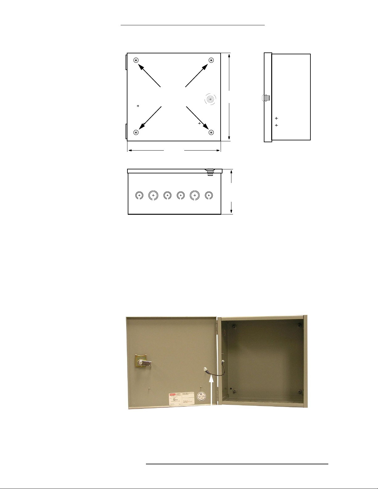
Mounting holes 12"
(30cm)
6"
(15cm)
12"
(30 cm)
24-10239-359 Rev. C 3
S300-DIN-S Hardware Installation
This document contains confidential and proprietary information of Johnson Controls
© 2017 Johnson Controls
Ground Strap
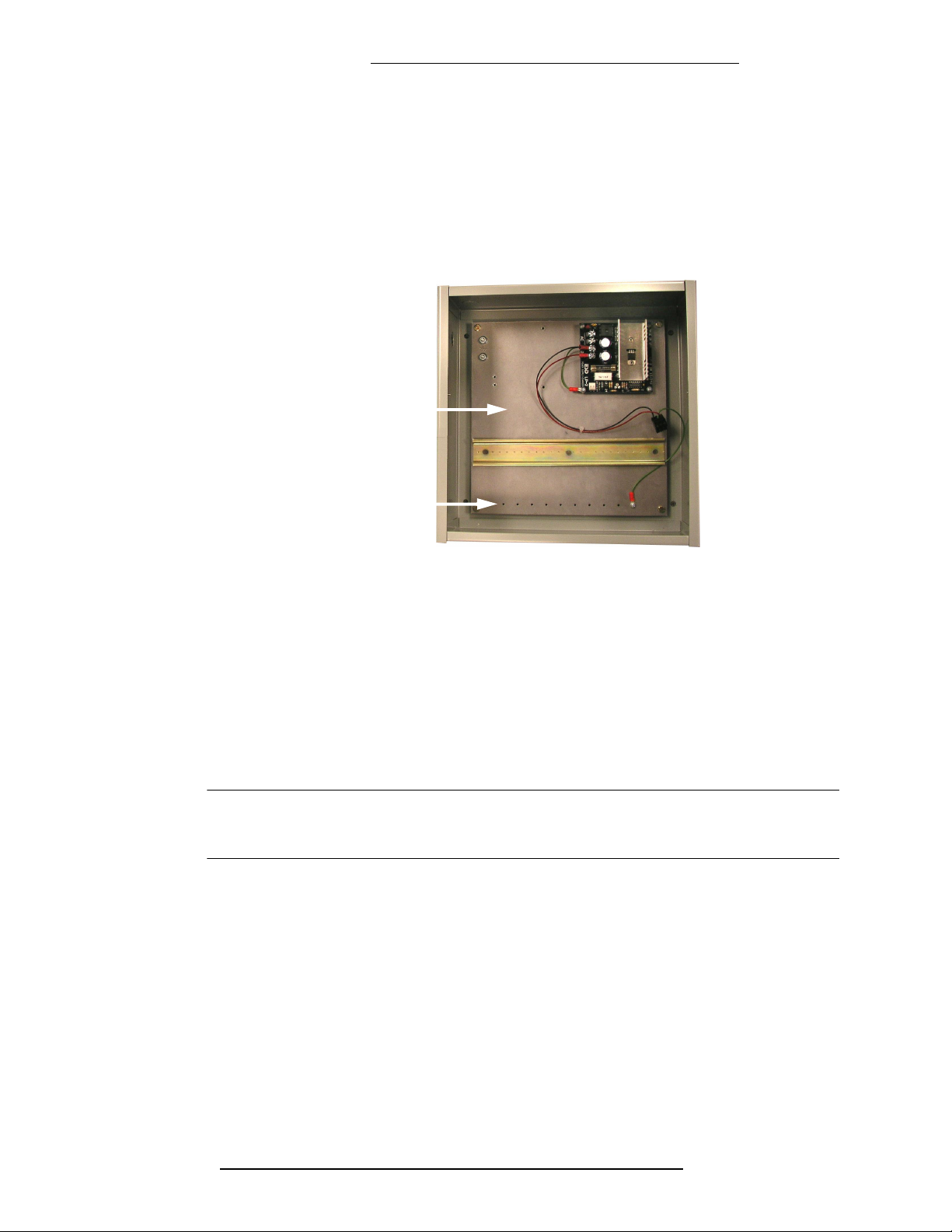
The ground strap is used to provide ground to the enclosure door.
To install the ground strap:
1. Put one ring terminal over the screw in the side panel and secure with a nut.
2. Put the other ring terminal over the screw in the enclosure door and secure
with a nut.
Mounted ground strap
Hardware Installation S300-DIN-S
4 24-10239-359 Rev. C
This document contains confidential and proprietary information of Johnson Controls
© 2017 Johnson Controls
Backplate
To mount the backplate:
1. Place the backplate inside the enclosure and align the backplate’s four
mounting holes with posts in the enclosure.
2. Secure the plate with nuts provided.
Installed
backplate
Grounding shield
termination points
Transformer (S300-XFMR)
The power supply in the small enclosure should be powered from the S300-XFMR
plug-in wall transformer. This transformer converts the 120 VAC line power to
24 VAC for the power supply. The transformer is rated at 24 VAC, 50 VA.
A transformer is required for each panel or enclosure to connect the power supply to
local power.
Cable for the transformer must be constructed using listed 18 AWG wire.
NOTE
For Canadian installations use Basler transformer part number BE116450AAA,
or Revere Industries model RT-2450SL/M.
Constructing the Transformer Cable
Use a 2-conductor listed 18 AWG cable between the connector and the transformer.
Connect the transformer to the nearest source of clean, unswitched AC power, and
ensure you use the correct voltage for your S300-DIN-S model. The transformer
output is 24 VAC, 50 VA. The input is 120 VAC. At the S300-DIN-S, connect AC
power as follows.
To connect AC power:
1. Put the cable from the S300-XFMR transformer through the knock out in the
left or top panel of the enclosure.

24-10239-359 Rev. C 5
S300-DIN-S Hardware Installation
This document contains confidential and proprietary information of Johnson Controls
© 2017 Johnson Controls
2. Connect the cable to the power supply.
3. A separate wire, 18AWG minimum, must be run from the dedicated ground
stud inside the S300-DIN-S enclosure to the building’s electrical ground. The
dedicated ground is marked with the symbol .
To verify DC ground:
1. Verify the wire connection between the power supply and COM on the
DIN-mounted device.
2. Verify the wire connection between the power supply and its standoff.
To verify chassis ground:
1. Verify the wire connection between the DIN-mounted device earth and the
backplate.
2. Verify the wire connection between the AC power source and the backplate.
3. Verify the wire connection between the DC and one of the power supply’s
mounting holes.
Power Supply (S300-DIN-S-PS)
S300-DIN-S-PS is a power supply to be used with S300-DIN-S. It is shipped already
mounted on the backplate. S300-DIN-S-PS is equipped with an AC power indicator.
A battery charger is included with the power supply package.
This power supply has a Listed 4A, 3AGC standard fuse.
Input
Continuous
output
AC LED
indicator
Battery
connector
Voltage
selector
Mounting hole
(one of 4)

Hardware Installation S300-DIN-S
6 24-10239-359 Rev. C
This document contains confidential and proprietary information of Johnson Controls
© 2017 Johnson Controls
To replace the S300-DIN-S-PS power supply:
1. Disconnect the AC input wires from the terminal block on the power supply.
2. Disconnect the battery cable.
3. Disconnect the two DC power wires.
4. Unscrew the power supply unit.
5. Mount the new power supply unit.
6. Ensure the voltage selector switch is set to 24.
7. Re-connect the cables in the reverse order.
IMPORTANT
Connect the AC power source last.
DIN-Mountable Devices
The DIN-mountable device (for example: a S300-DIN-RDR2S module, a CK722
controller, or a CK721-A controller) is mounted on the backplate’s DIN rail.
To mount a device, align it with the rail and snap it on (on some devices, you may
need to extend the white clips located on the bottom of the device prior to snapping
it on). To remove a device, pull down the bottom clips, then pull the bottom of the
device out and lift it up.
IMPORTANT
Do not connect the DC power cable to the DIN-mounted device until all
wiring is complete.
An S300-DIN-RDR2S module
mounted in the S300-DIN-S
Other manuals for S300 Series
6
This manual suits for next models
1
Table of contents
Other Johnson Controls Recording Equipment manuals

Johnson Controls
Johnson Controls Frick QUANTUM LX Instruction Manual

Johnson Controls
Johnson Controls Metasys Integrator MIG3500 Series User manual

Johnson Controls
Johnson Controls LDATFL2S01 User manual

Johnson Controls
Johnson Controls R45 Series Service manual

Johnson Controls
Johnson Controls Zone Terminal Assembly instructions



