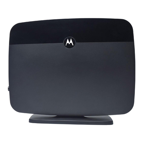
JetNet 3008G Series User manual

JetNet 3008G / 3005G Series
Industrial Full Gigabit Ethernet Switch
Quick Installation Guide
www.korenix.com
V1.0

Introduction
JetNet 3008G/3005G Industrial Full Gigabit Ethernet Switch, conforming IEEE 802.3,
802.3au and 802.3ab standard, supports 8 (5) 10/100/1000BaseTX. The JetNet
3008G/3005G adopts rugged metal case design to operate in harsh environments (-10~70oC);
It also provides IP-31 standard protection. It features one relay output to alarm users if a
port link fails or with the power fails. Alarms can be enabled/disabled by a dip switch. JetNet
3008G/3005G is recommended to be powered by DC 24V with 12~48V range from the 6-pin
removable terminal block.
Box contents
4JetNet 3008G/3005G Switch
4Quick Installation Guide
Mounting the Unit
4Din-Rail mount: Mount the din-rail clip screwed on the
rear of JetNet 3008G/3005G on the DIN rail.
Grounding JetNet 3008G/3005G Switch
There is one grounding screw on the bottom
side of JetNet 3008G/3005G. Connect
the earth ground screw of switch to the
grounding surface to ensure safety and
prevent noise. See, Figure-1
PW1
Alm
PW2
Alarm Control
port 1~8 power
Earth Ground
Screw
Earth Ground
Warning: Do not connect to AC line-Natural
Figure-1
Package contents Check List
JetNet 3008G / 3005G Series
Industrial Full Gigabit Ethernet Switch
Quick Installation Guide
www.korenix.com
V1.0

Wiring the Power Inputs
1. Insert the positive and negative wires
into the V+ and V- contact on the terminal
block connector.
2. Tighten the wire-clamp screws to
prevent the DC wires from being loosened.
See Figure-2
Notes: The recommended working voltage
is DC24V (DC12~ 48V).
Figure-2
Wiring the Earth Ground
Wiring the Relay Output
The relay output alarm contacts are in the
middle of the terminal block connector as
shown in the figure below.
By inserting the wires and set the DIP switch
of the respective Port Alarm to “ON”, relay
output alarm will detect any port failures, and
form a short circuit.
The alarm relay output is “Normal Open”.
See, Figure -3.
In an industrial environment, there might
have a lot of devices that generate
electromagnetic noise, such as AC motors,
electric welding machine, power generator.
These devices will generate electric noise or
surges that might disturb communications. To
prevent those noises, the switch should be
well earthed.
In the figure- shows how to make connection.
See, Figure -4.
Figure-3
Maximum 1A current / DC 24V
PW1
Alm
PW2
Alarm Control
port 1~8 power
Alarm
System
Extra Power
System
Figure-4
PW1
Alm
PW2
Alarm Control
port 1~8 power
Earth Ground
Screw
Earth Ground
Warning: Do not connect to AC line-Natural

Connecting to Network
Connecting the Ethernet Ports: Connect one end of an Ethernet cable into the UTP port of
JetNet 3008G/3005G, while the other end is connected to the attached networking device.
All UTP ports support auto MDI/MDIX function. The Speed LED will turn on for gigabit link
and turn off for 10/100Mbps link, the LNK/ACT LED will turn on for link up and blinking for
packet transmit and receive.
DIP Switch Settings for Alarm Relay Output
Korenix Customer Service
KoreCARE is Korenix Technology’s global service center, where our professional staffs are
ready to solve your problems at any time.
JetNet 3008G
Pin No. Description
JetNet 3005G
Pin No.
Pin 1 ~ 8
Pin 9
Pin 1 ~ 5
Pin 6
To enable port link down alarm at this port.
To disable port link down alarm at this port.
To enable power failure alarm.
To disable power failure alarm.
Status
ON
Off
ON
Off

CH
ญᨕ
JetNet 3008G/3005GܼܚᎹϮҹ㔥Ѹᤶᴎˈヺড়IEEE 802.3, 802.3au802.3abޚˈ
ᬃᣕ8/5Ͼ10/100/100Base TXッষDŽJetNet 3008G/3005G Ѹᤶᴎ䞛⫼മⱘ䪱ড়䞥㒧ᵘ
䆒䅵ˈ㛑ᙊࡷⱘᎹϮ⦃๗(-10~70oC)〇ᅮᎹˈヺড়IP31ᎹϮ䰆ᡸޚDŽᅗ䖬ᬃᣕϔ䏃㒻
⬉఼䄺䕧ߎˈৃ䩜ᇍᮁ㒓/ᮁ⬉⢊ᗕᦤկ⦄എ䄺᳡ࡵDŽℸ㒻⬉఼䄺ࡳ㛑ৃ䗮䖛Ѹᤶᴎࠡ
䴶ᵓⱘDipᢼⷕᓔ݇ࡼ݇䯁DŽJetNet 3008G/3005G ᴎ䑿ᑩ䚼㺙᳝ৃᢚ⬉⑤㒓ῑˈ
݊䕧ܹ⬉⑤㣗ೈᰃ12~48V ˈᓎ䆂䞛⫼〇ᅮⱘ24VⳈ⌕⬉Ў䆒կ⬉DŽ
ࣙ
4JetNet 3008G/3005G Ѹᤶᴎ
4ᖿ䗳ᅝ㺙ᇐ
ࣴ᠆х
4ᇐ䔼ᅝ㺙˖⫼㶎ϱᇚᇐ䔼།ᅮJetNet 3008G/3005G
ᴎ䑿㚠䴶ˈ✊ৢᇚᇐ䔼།Ϟᇐ䔼DŽ
JetNet 3008G / 3005G ޞᐰᨉఉ
JetNet 3008G/3005Gᴎ䑿ᑩ䚼᳝ϔϾഄ
㒓䖲㶎↡DŽᇚѸᤶᴎⱘഄ㒓㶎↡ഄˈৃ⹂
ֱ䆒Փ⫼ᅝܼˈᡫᴖ䆃ᑆᡄDŽখⳟ-1 PW1
Alm
PW2
Alarm Control
port 1~8 power
Earth Ground
Screw
Earth Ground
Warning: Do not connect to AC line-Natural
Дڳ᪇хྊת
JetNet 3008G / 3005G Series
Industrial Full Gigabit Ethernet Switch
Quick Installation Guide
www.korenix.com
V1.0
-1

ᆀྶᨉఉ
1. ᇚ⬉⑤ⱘℷ䋳ᵕᇐ㒓ߚ߿ᦦܹᴎ䑿ᑩ䚼⬉
⑤㒓ῑⱘV+ V- 㛮DŽ
2. ᇚ㒓།ᢻ㋻ˈ䰆ℶDC⬉⑤㒓ᤃࡼ㜅
㨑DŽখⳟ-2⊼: ⬉㣗ೈ(DC12~ 48V,
0.8A)ˈᓎ䆂⬉DC24VDŽ
-2
ᑖᆀݥஎᡚ᧢ՠᨉᐰ
㒻⬉఼䄺䕧ߎ䖲⚍ᰃ⬉⑤㒓ῑⱘЁ䭧ⱘ
ϔᇍ㛮ˈ བЁ᠔⼎ԡ㕂DŽ
䖲ᇐ㒓ˈᑊᇚᇍᑨッষⱘDIPᢼⷕᓔ݇㕂
ĀONāˈ㒻⬉఼䄺ࡳ㛑֓ৃҹẔ⌟ࠄッষ
ᮁ䖲ˈᑊᔶ៤ϔϾ⬉⑤ಲ䏃DŽℷᐌᚙމϟˈ㒻
⬉఼䄺㒓䏃ᰃᓔ䏃⢊ᗕDŽখⳟ-3.
-3
Maximum 1A current / DC 24V
PW1
Alm
PW2
Alarm Control
port 1~8 power
Alarm
System
Extra Power
System
-4
ޞᐰᨉఉ
ᎹϮ⦄എ⦃๗Ёˈৃ㛑Ӯ᳝䞣ѻ⫳⬉⺕ᑆ
ᡄⱘ䆒ᄬˈབѸ⌕⬉ࡼᴎˈ⬉⛞ᴎˈথ⬉
ᴎDŽ䖭ѯ䆒ѻ⫳ⱘ⬉⺕ᑆᡄ⌾⍠ᑆᡄഛৃ
㛑ᕅ䷓ࠄℷᐌ䗮䆃DŽЎ䰆ℶᑆᡄᕅડˈ䇋ᇚѸ
ᤶᴎℷ⹂ഄDŽ4ᦤկℷ⹂䖲㒓⼎՟DŽ
PW1
Alm
PW2
Alarm Control
port 1~8 power
Earth Ground
Screw
Earth Ground
Warning: Do not connect to AC line-Natural

ᒧᐰᨉఉ
ҹ㔥䖲˖ᇚUTPঠ㒲㒓ⱘϔッ䖲JetNet 3008G/3005Gҹ㔥⬉ষˈϔッ䖲ࠄ䳔
ܹⱘ㔥㒰䆒DŽ᠔᳝UTPッষᬃᣕ㞾䗖ᑨMDI/MDIXDŽᔧЎܚ䖲㒓ᯊˈ䗳⥛LEDᣛ⼎♃Ӯ҂
䍋ˈᔧЎ10/100M䖲㒓ᯊˈᣛ⼎♃Ӯ❘♁DŽLNK/ACT LEDᣛ⼎♃҂䍋㸼⼎ッষᏆ㒣䖲㒓ˈֵ
ো♃䮾⚕㸼⼎䆹ッষℷᬊথ᭄DŽܝষLEDᣛ⼎♃া᳝ϔϾˈᰒ⼎䖲㒓⢊ᗕ⌏ࡼ⢊ᗕDŽ
Korenix ۩َദ֩
KoreCAREᰃ⾥⋯⧚ᗱ㔥㒰⾥ᡔܼ⧗᳡ࡵЁᖗˈ៥ӀϧϮⱘᡔᴃҎ䱣ᯊޚ㾷ㄨᙼⱘ⭥
䯂DŽ⾥⋯⧚ᗱܼ⧗᳡ࡵЁᖗE-mail:[email protected]
DIP வኇԟᡷࣽ
JetNet 3008G
Pin No. ఞᨕ
JetNet 3005G
Pin No.
Pin 1 ~ 8
Pin 9
Pin 1 ~ 5
Pin 6
ࡼ䆹ッষⱘᮁ㒓䄺ࡳ㛑
݇䯁䆹ッষⱘᮁ㒓䄺ࡳ㛑
ࡼᮁ⬉䄺ࡳ㛑
݇䯁ᮁ⬉䄺ࡳ㛑
Ⴡઔ
ON
Off
ON
Off

DE
Einführung
Die industriellen Gigabit Ethernet Switches JetNet 3008G/3005G sind konform zum IEEE
802.3, 802.3au and 802.3ab Standard und unterstützen 8 (5) Ports mit 10/100/1000BaseTX.
Die JetNet 3008G/3005G besitzen ein robustes Metallgehäuse für den Betrieb in rauen
Umgebungen (-10~70oC). Es bietet auch einen Schutz nach IP-31 Standard. Die Switches
unterstützen einen Relaisausgang zur Alarmierung des Benutzers bei Ausfall eines
Ports oder der Spannungsversorgung. Die Alarme können mittels DIP-Schalter ein- bzw.
ausgeschaltet werden. Für den Betrieb des JetNet 3008G/3005G werden 24VDC empfohlen,
bei einem erlaubten Bereich von 12~48V. Der Anschluß erfolgt über einen abnehmbaren 6-Pin
Schraubklemmenblock.
Inhalt der Box
4JetNet 3008G/3005G Switch
4Quick Installation Guide
Befestigung
4Din-Schienenmontage: Den an der Rückseite des JetNet
3008G/3005G angeschraubten Din-Schienen Clip auf die
Din-Schiene klemmen.
Erdung des JetNet 3008G/3005G Switch
Der JetNet 3008G/3005G besitzt eine
Erdungsschraube auf der Unterseite des
Gerätes. Diese Erdungsschraube mit Masse
verbinden, damit die elektrische Sicherheit
gegeben ist und Störungen vermieden
werden. Siehe, Abb. -1
PW1
Alm
PW2
Alarm Control
port 1~8 power
Earth Ground
Screw
Earth Ground
Warning: Do not connect to AC line-Natural
Figure-1
Check-Liste zum Lieferumfang
JetNet 3008G / 3005G Series
Industrial Full Gigabit Ethernet Switch
Quick Installation Guide
www.korenix.com
V1.0

Anschluss der Spannungsversorgung
1. Den positiven und den negativen
Draht in die V+ und V- Anschlüsse des
Anschlußblocks stecken.
2. Die Schrauben fest anziehen, um ein
Ablösen der Leitungen zu verhindern. Siehe
Abb. -2
Beachte: Die empfohlene Betriebsspannung
beträgt 24 VDC (12-48 VDC)
Figure-2
Anschluss der Masse
Anschluss des Relaisausgangs
Die Relaisausgangskontakte befinden sich in
der Mitte des Schraubklemmenblocks wie in
untenstehender Abb. zu sehen.
Mit dem Anschluß der Drähte und der Einstellung
des DIP-Schalters für den entsprechenden Port
auf „ON“, werden Fehler an diesem Port erkannt
und der Relaisausgang kurzgeschlossen. Der
Relaisausgang ist „Normally Open“. Siehe Abb. -3
In industrieller Umgebung gibt es oft
Geräte wie Motoren, Schweißgeräte,
Transformatoren, die elektromagnetische
Störungen hervorrufen. Diese Geräte
erzeugen elektromagnetische Strörungen,
die dann ihrerseits die Kommunikation
beeinträchtigen. Um solche Störungen zu
vermeiden, sollten die Switches sorgfältig
geerdet werden. Abb. –4 zeigt die Anschlüsse
Figure-3
Maximum 1A current / DC 24V
PW1
Alm
PW2
Alarm Control
port 1~8 power
Alarm
System
Extra Power
System
Figure-4
PW1
Alm
PW2
Alarm Control
port 1~8 power
Earth Ground
Screw
Earth Ground
Warning: Do not connect to AC line-Natural

Verbindung mit dem Netzwerk
Verbinden der Ethernet Ports: Das eine Ende des Ethernet Kabels in den UTP Port des
JetNet 3008G/3005G stecken, das andere Ende mit dem angeschlossenen Netzwerkgerät
verbinden. Alle UTP Ports unterstützen Auto-MDI/MDIX Funktion. Die Speed LED leuchtet
bei Gigabit-Verbindung konstant und ist bei 10/100Mbps Verbindung aus. Die LNK/ACT
LED leuchtet bei Verbindung konstant und blinkt bei Sendung und Empfang von Paketen.
DIP Schalter Einstellungen für den Relaisalarmausgang
Korenix Kunden Service
KoreCARE ist Korenix Technology’s globales Service Center, wo unsere professionellen
Mitarbeiter zu jeder Zeit bereit sind Ihre Probleme zu lösen.
JetNet 3008G
Pin No. Beschreibung
JetNet 3005G
Pin No.
Pin 1 ~ 8
Pin 9
Pin 1 ~ 5
Pin 6
Port link down Alarm an diesem Port einschalten
Port link down Alarm an diesem Port ausschalten
Spanungsversorgungsfehler Alarm einschalten
Spanungsversorgungsfehler Alarm ausschalten
Status
ON
Off
ON
Off
This manual suits for next models
1
Table of contents
Languages:
Other JetNet Network Router manuals