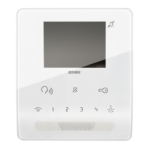
ITS Telecom Pancode VoIP Assembly instructions

Pancode VoIP
Pantel VoIP
Access Control Door Phones
Installation and
Programming Manual
October 2007
Version 2 Pre-Release 2

Pancode VoIP/Pantel VoIP Access Control Door Phones
Installation and Programming Manual
NOTICE
This publication refers to the PANCODE IP and Pantel IP Door Access Control devices, Release 2.
Additional copies of this manual may be obtained from ITS Ltd. Reproduction of this manual or parts
thereof without written permission from ITS is strictly prohibited.
ITS Ltd. reserves the right to modify the hardware and software described herein without prior notice.
However, changes made to the hardware or software described do not necessarily render this
publication invalid.
WARRANTY
In the event that the product proves to be defective in workmanship or materials within a period of
one year from date of shipment, ITS Ltd. shall repair or replace the same at its discretion. Transportation
will be the responsibility of the dealer/distributor.
Under no circumstances shall ITS Ltd. be liable for consequential or special damages, loss
of revenue or user/dealer expenses arising out of or in connection with the use or
performance of the product, whether base on contract, tort or any other legal agreement.
The following shall void the above warranty: malfunctions resulting from fire, accident, neglect, abuse or
acts of God; use of improper electrical power; or repair of, tampering with or alteration of the product
by anyone other than ITS authorized.

Pancode VoIP/Pantel VoIP Access Control Door Phones
Installation and Programming Manual
1
Table of Contents
1. Introduction ...............................................................................................................................................2
1.1 Pancode VoIP/Pantel VoIP Kit Contents............................................................................................3
2. Physical Description....................................................................................................................................4
2.1 Pancode VoIP Front Panel ................................................................................................................4
2.2 Pantel VoIP Front Panel....................................................................................................................5
3. Installation .................................................................................................................................................6
4. Pancode VoIP/Pantel VoIP Schematic Setup ................................................................................................7
5. Installing the Pantel VoIP/Pancode VoIP ......................................................................................................8
6. Adjacent Access Control Device ...............................................................................................................11
7. Programming ...........................................................................................................................................13
7.1 Searching for a Device in LAN........................................................................................................13
7.2 Application Interface .....................................................................................................................14
7.3 System Parameters ........................................................................................................................15
7.4 VoIP Dialing settings......................................................................................................................18
8. Technical Specification .............................................................................................................................21

Pancode VoIP/Pantel VoIP Access Control Door Phones
Installation and Programming Manual
2
1. Introduction
This guide provides installation and programming instructions for the following products:
Pancode VoIP outdoor piezo keypad unit
Pantel VoIP outdoor piezo keypad unit
The Pancode VoIP and Pantel VoIP are smart wall-mounted access control door phones connected to a local
Voice Over IP (VoIP) network of a VoIP PBX, allowing door entry control. They are available for outdoor
installation in an aluminum unit with a piezo keypad. As an option, these units can be equipped with an internal
black & white or color high-quality pinhole camera.
The Pancode VoIP and Pantel VoIP have the following features:
Feature Pancode VoIP Pantel VoIP
Integration with local LAN and VoIP networks UU
Authorized registration with existing VoIP switching system (Proxy) UU
Two different operation modes:
Standard – for direct dialing to any destination number
Speed-dial – for one-touch dialing to internal or external subscribers
UX
Automatic busy & disconnect detection UU
Door opening from any extension UU
Door opening from Bypass Switch button UU
Programmable day and night destinations UU
High quality speakerphone with separate volume control UU
Entry access code (supports up to ten codes) UX
Works in conjunction with card readers and security devices UU
Programming via Ethernet interface using a web-based GUI application UU
Acoustic echo canceller UU
Automatic gain control (AGC) UU
SRTP (encryption and authentication) UU
Support for video over VoIP (optional) UU
Smart looking durable design UU

Pancode VoIP/Pantel VoIP Access Control Door Phones
Installation and Programming Manual
3
1.1 Pancode VoIP/Pantel VoIP Kit Contents
The contents of the Pancode VoIP/Pantel VoIP are as follows:
Pancode VoIP or Pantel VoIP unit
External 12V AC power supply
Ethernet cable
Installation CD

Pancode VoIP/Pantel VoIP Access Control Door Phones
Installation and Programming Manual
4
2. Physical Description
The Pancode VoIP and Pantel VoIP are attached to the wall using a bracket and screws. These units are
hardwired and powered by an external 12V AC transformer, included in the package. The Pancode VoIP and
Pantel VoIP dimensions are:
Height: – 19.4 cm
Width: – 10.2
2.1 Pancode VoIP Front Panel
The front panel of the Pancode VoIP unit contains a built-in speaker, a microphone and a touch-keypad
(Figure 1).
Speaker
Keypad
Microphone
Figure 1. Pancode VoIP Front Panel

Pancode VoIP/Pantel VoIP Access Control Door Phones
Installation and Programming Manual
5
2.2 Pantel VoIP Front Panel
The front panel of the Pantel VoIP unit contains a built-in speaker, a microphone and a touch-keypad (Figure 2).
Speaker
Call Button
Microphone
Figure 2. Pantel VoIP Front Panel

Pancode VoIP/Pantel VoIP Access Control Door Phones
Installation and Programming Manual
6
3. Installation
The Pantel VoIP/Pancode VoIP is mounted on the provided installation bracket. This mounting bracket should be
installed as shown in Figure 3.
Figure 3. Installation Bracket
To install the wall bracket:
a. Measure and mark the location on the wall where the holes will be drilled for the mounting bracket.
b. Drill the holes and insert the wall anchors into the holes.
c. Attach the mounting bracket using the provided wall screws.

Pancode VoIP/Pantel VoIP Access Control Door Phones
Installation and Programming Manual
7
4. Pancode VoIP/Pantel VoIP Schematic Setup
The Pancode VoIP/Pantel VoIP unit is connected to the VoIP PBX as a SIP extension or via any IP router (Network
HUB, Switch etc). The unit powers the door lock, provided it is powered by an external supply and not PoE.
Figure 4 details the unit schematic setup.
Extension
Door Lock
TV Monitor
Pancode VoIP/
Pantel VoIP
PBX
V
oIP Network/
LAN
Figure 4. Schematic Setup

Pancode VoIP/Pantel VoIP Access Control Door Phones
Installation and Programming Manual
8
5. Installing the Pantel VoIP/Pancode VoIP
The Pantel VoIP/Pancode VoIP can be installed as an individual access control or used with adjacent access-
control devices, such as card reading devices (see Section 6).
The provided 12V AC external power supply should not be located further than 10m (30ft) from the unit.
These units also support Power Over Ethernet (PoE), meaning that they could operate when connected to
Ethernet without mains. However, the current provided by the PoE supply is insufficient for opening a
door. If your system is equipped with door lock relay, make sure to use the external supply.
Figure 5 shows the terminal locations on the wire connector provided with the unit. This connector is attached at
the base of the internal component. All wiring to the unit is attached to the wire connector.
There may be LINE pins in the connector, but they are not active with
this product and cannot be used. When holding the unit as displayed
in Figure 6, the first pin from the right is the first ~12V pin.
The Pantel VoIP/Pancode VoIP supports a bypass switch installation. This allows opening the door with a
hardwired switch. A bypass switch should be connected to the SW and /SW terminals.
Bypass Switch (SW)
Bypass Switch (/SW)
Connect
to an
External
Device
Connec
t
to Door
Lock
Relay
option 1
option 4
option 3
option 2
Contact
Detection
N.C.
N.O.
CMN
DLR
/DLR
~DLR
~DLR
~12V
~12V
Figure 5. Connectors Scheme
Other manuals for Pancode VoIP
1
This manual suits for next models
1
Table of contents
Other ITS Telecom Intercom System manuals