ISOTRON 160C User manual

INSTRUCTION MANUAL
FOR THE
ISOTRON 160C
ALSO AM BROADCAST BAND MODELS
MANUFACTURED BY
BILAL COMPANY
137 MANCHESTER DR.
FLORISSANT, CO. 80816
PH: 719/687-0650

TABLE OF CONTENTS
ASSEMBLY INSTRUCTIONS 2
TUNING 4 - 5
ASSEMBLY DIAGRAM 6 - 11
FINDING THE RESONANT POINT 12 - 13
TRIMMING THE COIL 14
COMPENSATION FOR LOCATION 15 - 16
SIDE TOWER MOUNTING 17
GROUNDING 17
THE USE OF A TUNER 18
POWER RATING 19
SINGLE FEEDLINE OPERATION 20
PERFORMANCE 21
WARRANTY 22

2.
INTRODUCTION
The Isotron 160C will be assembled on the mast from the
top down. You will need a metal mast to support the
antenna during assembly. A temporary mast can be used if
you are going to relocate the antenna.
The Assembly instructions will refer to diagrams 1 - 5.
PARTS LIST (See Fig. 1-5 for identification)
1. TOP PLATE #11
2. BOTTOM PLATE #1
3. BOTTOM SUPPORT #2 (4 HOLES, 7/8" OD,
NON-METALLIC).
4. MIDDLE SUPPORT #6 (3 HOLES " " ).
5. TOP SUPPORT #13 (4 HOLES " " ).
6. COIL #4 WITH 1/4" CROSSBAR.
7. BOTTOM COIL SUPPORT ROD #3, 8 1/2" X 1/4"
SOLID ROD.
8. TOP COIL SUPPORT ROD #5, 60Z' X 1/4 " SOLID
ROD.
9. TUNING ROD #14, 36" X 1/4" SOLID ROD, NO
THREADS.
10. GROUNDING WIRE #15.
11. TUNING ROD BRACKETS (TWO) #9 AND #12.
ASSEMBLY
1. Attach BOTTOM SUPPORT #2 to BOTTOM PLATE #1.
Use one 1\4" x 1 1\2" bolt with a GROUNDING WIRE #15
and nut. Use the holes that are closest to the mast, do not
tighten at this time. See FIG. 1. NOTE: PLATE #1 has the
SO-239 Connector mounted on it.
2. Attach COIL #4 to BOTTOM COIL ROD #3. Each end
of #3 should have a nut threaded to the end of the
threads. The end with the shorter threads is screwed into
the COIL #4 bottom. The nut is tightened to the coil to
secure it. See Fig. 1 & 2.
3. Mount the COIL #4 to the BOTTOM PLATE #1 by
inserting BOTTOM COIL ROD #3 into the hole farthest
from the mast through #2 and #1. Use a second nut to
secure. Now you can snug up both nuts on the BOTTOM
SUPPORT #2. See Fig. 1.
4. Put a stop nut on each end of the COIL CROSS BAR.
Insert the COIL CROSS BAR into the side holes and secure
with a second nut. See Fig. 2. NOTE: There may be some
downward tension on the bar.

3.
5. Attach the wire pigtail from the SO-239 Connector and
the wire pigtail from the bottom of COIL #4 to the 8/32
stud at the bottom of the coil. Remove one nut, put the
solder lugs on and replace the nut and secure. See Fig. 1
and 5.
6. Put one nut on one end of the TOP COIL ROD #5. Put
this
threaded end through the wire eye at the top of the COIL.
Attach a second nut, then screw the TOP COIL ROD #5
into the COIL. With the threads most of the way into the
coil, tighten the nut against the coil, then tight the nut
above the wire eye. See Fig. 1 and 3.
7. Slide the MIDDLE SUPPORT #6 on to the TOP COIL
ROD #5. Use the single hole at the end of the support.
This support will be at 1" above the adjacent nut on the
COIL.
8. At the opposite end of the 30" rod that is screwed into
the coil, screw a 1/4" nut about 1/2 way down on the
threads. Next screw the 1/4" x 7/8" coupling nut so it is
against the standard nut. Snug these 2 nuts together. Set
this section aside and go to the top section for assembly.
9. Slide TUNING ROD BRACKET #9 onto the second TOP
COIL ROD #5, leave it loose. Set this aside. See Fig. 3.
10. Attach the TOP PLATE #11 to TOP SUPPORT #13.
Use a 1/4" x 1 1/2" Bolt with a nut in the hole closest to
the mast, but do not secure. See Fig. 3.
11. Slide the second TOP COIL ROD #5 through the
U-JOINT #10. If needed you can loosen the set screw, but
re-tighten once everything is in place. See Fig. 3
12. Slide the second TUNING ROD BRACKET #12 on to
the TOP COIL ROD #5. See Fig. 3.
13. Thread a 1/4" nut all the way down on the top of
second TOP COIL SUPPORT #5. Then add a flat washer
from the hardware packet, then slide into the hole
attaching the TOP SUPPORT #13 and TOP PLATE #11.
Secure with a second nut, but leave it loose. Secure the 1
1/2 " Bolt previously installed in step #11. See. Fig. 3.

4.
14. Mount a U-bolt at the top of the mast where the
antenna is to be. See Fig. #6.
15. Mount the TOP SUPPORT #13 (with Top Plate, 30"
Rod and Tuning rod brackets) on to the top U-BOLT. Put
a second set of nuts from the U-BOLT Packet and leave
them a little loose against the outside of #13. See Fig. #6.
Use an open end wrench to tighten securely the nuts next
to the mast and metal strap of the U-bolts. Tighten so the
strap forms to the mast. Then secure the second set of
nuts against the #13 Top Support.
16. 76 inches down from the top U-Bolt mount the bottom
U-Bolt in the same manner.
17. 20 1/2" up from the bottom U-Bolt mount the center
U-Bolt in same manner.
18. Mount SUPPORTS #2 and #6 on the U-bolt. Be sure
they are
parallel, then secure with a second nut from the U-BOLT
package and tighten as described in step 15.
19. The two 30" Coil Support Rods #5 should meet. Screw
a 1/4" regular nut onto the top rod. Then Screw the rod #5
onto the 1/4" x 7/8" Coupling nut until it stops. Then
secure it by tightening the 1/4" regular nut against it.
20. Tighten the 1/4" nut at the top where #5 attaches to
the Top Plate #11
21. Slide the TUNING ROD #14 through the two TUNING
ROD BRACKETS #9 and #12. #12 will always be
positioned at the top of rod #5. #9 will always move with
the bottom of the TUNING ROD #14. When tuning is
complete, secure the 8/32 nuts on the brackets.
TUNING
1. The Isotron 160C should be mounted as high and in the
clear as possible on a metal mast. See Fig. 6 on page 10 for
the proper installation of the U-BOLT Assemblies.
2. 50 ohm coax should be connected to the SO-239
Connector on the antenna. The coax should either be
secured to the mast with tape or stand-offs. A neat run
with no excess should go to the radio.

5.
3. Lengths of coax that are an exact 1/4 wavelength should
be avoided. This length would have the velocity factor
considered for your type of coax. This is only for the first
1/4 wavelength. Adding a few feet of coax to avoid this
length is fine.
4. No tuning devices should be in the line for the initial
tune up. These can be used later if desired.
5. Maximum resonant frequency will be with the TUNING
ROD #14 in the lowest position or removed.
6. To decrease the resonant frequency, raise the TUNING
ROD #14 according to what you want. Secure the Brackets
#9 and #12
keeping them positioned properly. Refer to step 17.
7. Start at low power and graph your SWR across the 160M
band.
Locate the minimum SWR. This is your resonant point.
Please read over the section on "FINDING THE
RESONANT POINT".
8. For frequencies higher than 2.0 Mhz see the section on
"TRIMMING THE COIL".
9. If the minimum SWR is not low enough, then refer to
the topic "COMPENSATION FOR VARIATION IN
LOCATION" for the minor
adjustment.
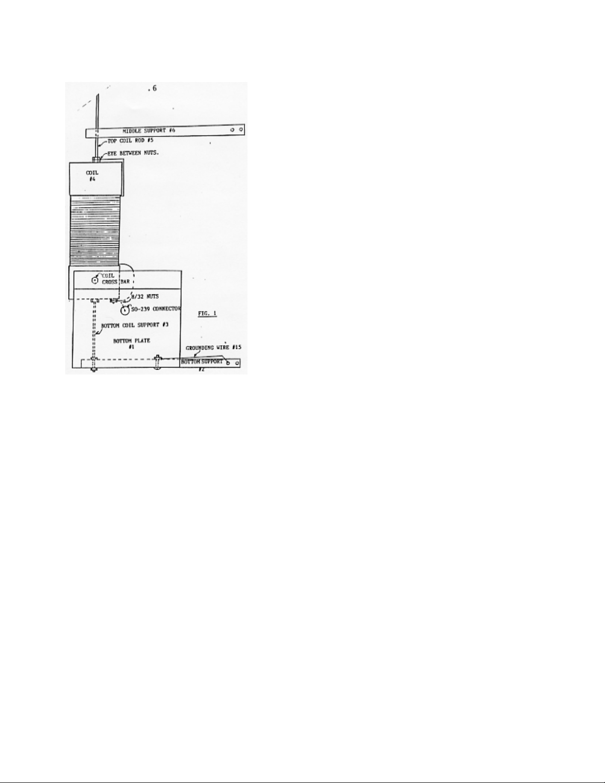

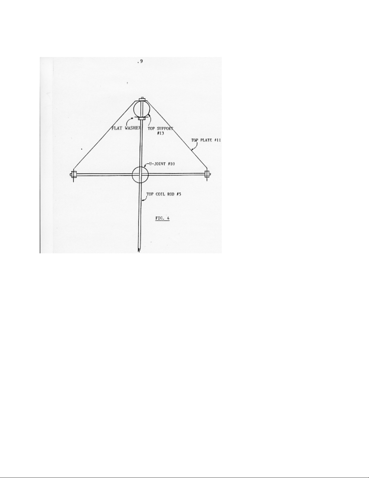
Table of contents


