Iron Bow MEDVIEW-C-30X-A01 User manual

Iron Bow MedView
™
Installation and User Guide
For use with Cisco MedView Model Number:
MEDVIEW C 30X A01
(Un Switched Version)
Document # DOC UG MEDVIEW C30X A
Version 6.0
2/8/2021

Copyright 2021 Iron Bow Technologies 2
Copyright © 2021 Iron Bow Technologies
All Rights Reserved.
Specifications su ject to change without notice.
For general inquiries, contact:
Iron Bow Healthcare Solutions
2303 Dulles Station Boulevard, Suite 400
Herndon, VA 20171
Toll: 800.338.8866
Tel: 703.279.3000
www.iron owhealthcare.com
For support, contact:
Iron Bow Client Service Center
Toll: 833.476.6269 (833.IRONBOW)
Email: CSC@iron ow.com

Copyright 2021 Iron Bow Technologies 3
Safety & Maintenance
For your protection, please read these safety instructions completely before operating the equipment and keep this manual for
future reference. The information in this summary is intended for persons who operate the equipment as well as repair or
servicing personnel. Carefully observe all warnings, precautions and instructions on the apparatus, or the ones described in the
operating instructions and adhere to them. Also, adhere to safety guidelines found in manuals for any peripheral equipment.
the equipment.
Care and Handling
Water and moisture Do not operate the equipment under or near water, or in areas with high humidity.
Cleaning Unplug the apparatus from the wall outlet before cleaning. Do not use liquid cleaners or aerosol cleaners, follow
cleaning instructions provided
Ventilation Do not block any of the ventilation openings of the apparatus. Install in accordance with the installation
instructions.
Grounding or Polarization – use the power cord provided with this system, do not defeat the safety purpose of the
grounding type plug. A grounding type plug has two blades and a third grounding prong. The third prong is provided for
your safety. If the provided plug does not fit into your outlet, consult an electrician.
Plug Acts as Disconnect Device The socket outlet to which this apparatus is connected must be installed near the
equipment and must always be readily accessible.
Lightning Unplug this apparatus during lightning storms or when unused for long periods of time.
Network cables CAUTION To reduce the risk of fire, use only No. 26 AWG or larger telecommunication line cord.
Power Cord Protection Route the power cord so as to avoid it being walked on or pinched by items placed upon or
against it, paying particular attention to the plugs, receptacles, and the point where the cord exits from the apparatus.
Attachments Only use attachments as recommended by the manufacturer. When a cart is used, use caution when moving
the cart/apparatus combination to avoid injury from tip over.
Storage If you need to store the system, ensure that it is stored in a controlled environment to avoid damage:
Non-operating temperature: -20°C –60°C
Non-operating humidity (non-condensing): 10%–9 %
Repacking – Do not throw away the carton and packing materials. They may be required in the event that you need to
move the system to an alternate location, or return the system for maintenance.
“WARNING – Do not modify this equipment without authorization of the manufacturer.”
Servicing Do not attempt to service the apparatus yourself as opening or removing covers may expose you to dangerous
voltages or other hazards, and will void the warranty. Refer all servicing to qualified service personnel. If the equipment is
damaged, unplug the apparatus from the outlet and refer servicing to qualified personnel:
When the power cord or plug is damaged or frayed
If liquid has been spilled or objects have fallen into the apparatus
If the apparatus has been exposed to rain or moisture
If the apparatus has been subjected to excessive shock by being dropped, or the cabinet has been damaged
If the apparatus fails to operate in accordance with the operating instructions.
Cleaning Instructions
CAUTION
United States Canada
Plug Type Grounding type 3 Pole Plug Grounding type 3 Pole Plug
Cord Type SVT3 x 18 AWG SVT3 x 18 AWG
Minimum Cord Set Rating 10A/1 5V 10A/1 5V
Safety Approval UL/CSA CSA

Copyright 2021 Iron Bow Technologies 4
Due to the close proximity of electrical power and equipment, flammable cleaners should never be used to clean these
products!
The surface materials of the unit are primarily powder coated aluminum and are durable and easy to maintain, however they
can stain and discolor, so test any cleaners in an inconspicuous place before using.
Do not allow any liquids to enter the unit, drip down the monitor or accumulate on any surface.
Please refer to the respective Materials Safety Data Sheets (MSDS) for detailed descriptions for each product from its
manufacturer.
Never use steel wool, Scotch Brite™ or other abrasive materials to clean the product.
Use extreme caution when cleaning the camera, as it is delicate and easily broken.
Use extreme caution when cleaning a display monitor, as they are easily damaged if too much pressure is applied.
General Procedure
1. Verify the system is unplugged from the AC Power outlet before cleaning.
2. Use a soft, clean microfiber cloth or manufacturer supplied disposable cloth for all applications, particularly when cleaning
lenses and monitors. Do not spray liquids directly on the surface.
3. Utilize appropriate cleaners for the surface being cleaned.
4. Allow equipment to fully dry prior to plugging into a power source.
5. To facilitate an effective infection control program and ensure proper performance, routinely clean, disinfect, and maintain
products in accordance with approved procedures. Specifically, the hospital’s Infection Control Administrator should be
consulted for cleaning procedures and processes.
Suggested chemical cleaners/disinfectants/solutions for MedView:
Chassis cleaning
o Non Abrasive Soap/Detergent: Generally, water and mild non abrasive soap/detergent or isopropyl alcohol can be
used routinely on CLINiC or MedView products to maintain proper cleanliness.
o Where infection control is required
A 10% or less bleach solution can be used to disinfect. Remove residue using a clean damp (water) cloth.
Branded chemical disinfectant products (test specific product on a sample surface before general use)
Metrex CaviWipes
Clorox Germicidal Wipes
Camera body (not the lens)
o Do not use any of the following chemicals or any solutions that contain: chlorine (bleach), acetone, peroxides,
ammonia, ethyl alcohol, benzene, toluene, ethyl acid, or methyl chloride.
o Branded, ammonia free LCD cleaning products
Zeiss Pre Moistened Lens Cleaning Wipes
CloroxPro Clean Screen Wipes
o Up to 50:50 isopropyl alcohol to distilled water mixture for general cleaning, using soft microfiber cloth
o Use 70:30 isopropyl alcohol and distilled water mixture for infection control, using soft microfiber cloth
Camera Lens
o Use only branded, ammonia free cleaning wipes specifically designed for lens cleaning
Zeiss Pre Moistened Lens Cleaning Wipes
Notes and Caution
Use extreme caution when cleaning the camera, do not manually move the camera when it is powered. Damage caused by
improper cleaning will void the Iron Bow warranty.
Do NOT use mineral spirits, acetone, paint thinners, or abrasive cleansers, or any other flammable, harsh or toxic chemicals.
This document provides general guidelines only. Direction for proper cleaning and infection control is the responsibility of
local authority and hospital administration.
Iron Bow is not responsible for improper cleaning or disinfection in any and all circumstances.

Copyright 2021 Iron Bow Technologies 5
Electrical Safety Information
Compliance is required with respect to the voltage, frequency, and current requirements indicated on the manufacturer’s
label. Connection to a power source different than those specified herein will likely result in improper operation or damage to
the equipment, or pose a fire hazard.
There are no user serviceable parts inside this equipment. There are hazardous voltages generated by this equipment that
constitute a safety hazard. Service should be provided by a qualified service technician only. Contact a qualified electrician or
the manufacturer if there are questions about the installation prior to connecting the equipment to mains power.
O erating Guidelines
Mounting Guidelines
The system is designed for attachment to the top of a display using the optional mounting bracket system, or can be wall or
ceiling mounted using the system base attachment points and suitable third party brackets / mounts. Care should be taken to
ensure that any supporting device is fir for purposes and is capable of supporting the weight of the system and any attached
peripherals/cables.
Connecting Peri heral Equi ment
It is recommended that an AC isolation transformer is used if the system is to be used with any external peripheral that may
have direct skin contact. It is also recommended that any external device that may have skin contact are individually certified
for such use to avoid risk of injury.
Any AC powered peripheral device must be connected to a separate AC outlet suitable for use with the device as defined by
the manufacturer’s specification information. In addition, AC power strips or extension cables should not be used with this
system.
Ambient Tem erature Guidelines
Operating temperature: 5°C –35°C (ambient temperature)
Operating humidity: 20%–80% (RH)
Non operating temperature: 20°C –60°C
Non operating humidity (non condensing): 10%–90%

Copyright 2021 Iron Bow Technologies 6
Contents
Introduction 8
System Descri tion 9
System Installation 10
Wall Mounting 11
Inverted Operation 11
Ceiling Mounting 12
Display Mounting 12
Attaching MedView to Display Mounting Bracket 14
Attaching to Display 17
System Connections 21
System Configuration 22
Codec Configuration 22
Getting Started 22
Powering On the MedView 23
MedView Standby Mode 23
Waking Up the MedView 23
Powering Off the MedView 23
Handling the MedView 23
MedView Administration 25
Accessing the Codec Web Interface 25
Changing Standby Settings 26
Changing Conference Settings (Tethered Remote Only) 27
System Auto Dial Operation (Tethered Remote Only) 28
A endix.1. Physical and Electrical S ecifications 29
A endix.2. Tethered Remote Volume Control 30
Connecting Tethered Remote Volume Control to MedView System 30
Camera Reset Function 30
A endix.3. Tethered Remote Control 31
Control Panel Functions 32
Connecting Tethered Remote Control to MedView System 32
Managing Calls 33
Managing Video Settings 34
Managing Audio Settings 36
A endix.4. O tional Ceiling Micro hone 37
A endix.5. MedView Base Mounting Bracket 38
A endix.6. MedView 200mm/300m Ada tor Plate 39

Copyright 2021 Iron Bow Technologies 7
Figures
Figure
1 Iron Bow MedView System 8
Figure
2 MedView System Components 9
Figure
3 MedView System Dimensions 10
Figure
4 MedView Attached to Commercial Wall Bracket 11
Figure
5 Camera Orientation Switch 11
Figure
6 Typical MedView Ceiling Mount 12
Figure
7 MedView Mounting Bracket Kit 13
Figure
8 MedView Mounted Above Display 14
Figure
9 MedView 100mm Mounting Bracket 14
Figure
10 MedView Mounting Bracket Top Plate Access Holes 14
Figure
11 Attaching MedView to Mounting Bracket 15
Figure
12 Alternate Mounting Plate Attachment Locations 15
Figure
13 Center Line Attachment Locations 16
Figure
14 MedView Mounting Bracket Height Adjustment 17
Figure
15 Mounting MedView to Display VESA Mount 17
Figure
16 MedView Adaptor Plate 18
Figure
17 MedView Mounting Bracket and Adaptor Plate Layouts 18
Figure
18 Assembling the 200mm/300mm Mounting Bracket 19
Figure
19 MedView System Connections 21
Figure
20 Internal LED Indicators 22
Figure
21 "On Air" Indicator 23
Figure
22 Camera Fault Indicator 23
Figure
23 Resetting the Camera 24
Figure
24 Tethered Remote Volume Control 30
Figure
25 Connecting Tethered Remote Volume Control 30
Figure
26 Camera Reset 30
Figure
27 Tethered Remote Control System 31
Figure
28 Tethered Remote Control Cradle 31
Figure
29 Tethered Remote Control Functions 32
Figure
30 Connecting the Tethered Remote Control 32
Figure
31 Ceiling Microphone Assembly 37
Figure
32 Ceiling Microphone Mounting Location 37
Figure
33 Ceiling Microphone Mounting Dimensions 37

Copyright 2021 Iron Bow Technologies 8
Introduction
The MedView family of products from Iron Bow Healthcare Solutions consists of
purpose built telehealth devices that integrate with existing in room equipment to enable
the delivery of clinical healthcare from a distance. This user guide covers the assembly
and installation of the Iron Bow MedView, part # MEDVIEW C 30X A01.
The MedView includes a video codec, a high definition video camera, built in
microphone, and complete audio sub system including full duplex echo cancellation,
amplifier and dual system loudspeakers.
The basic system functions of the MedView are designed to be fully automated with
optional control devices being available for different workflows. These include a multi
function tethered remote controller, as well as a simple tethered remote volume control.
A standard Cisco Touch 10 controller can also be connected to the MedView, if required.
This user guide covers the functionality and installation of the Iron Bow MedView
Figure 1. Iron Bow MedView System
You can find additional MedView resources and information about support and other
related telehealth services at www.ironbowhealthcare.com.

Copyright 2021 Iron Bow Technologies 9
System Description
The primary components of the MedView are shown below:
Figure
2
.
MedView
system
components
Descri tion:
1. 30X/12X Optical/Digital Pan/Tilt/Zoom Camera
2. Low Light Level Detector
3. Infra Red Illuminator
4. Integrated System Speakers
5. Call Status Indicator
6. Integrated Microphone
7. Removable cap to access camera inversion switch
8. Cable Tie Bar
9. Integrated Cisco Webex Room Kit Plus (In custom enclosure)

Copyright 2021 Iron Bow Technologies 10
System Installation
The MedView system can be mounted above, or below, a display as well as wall or
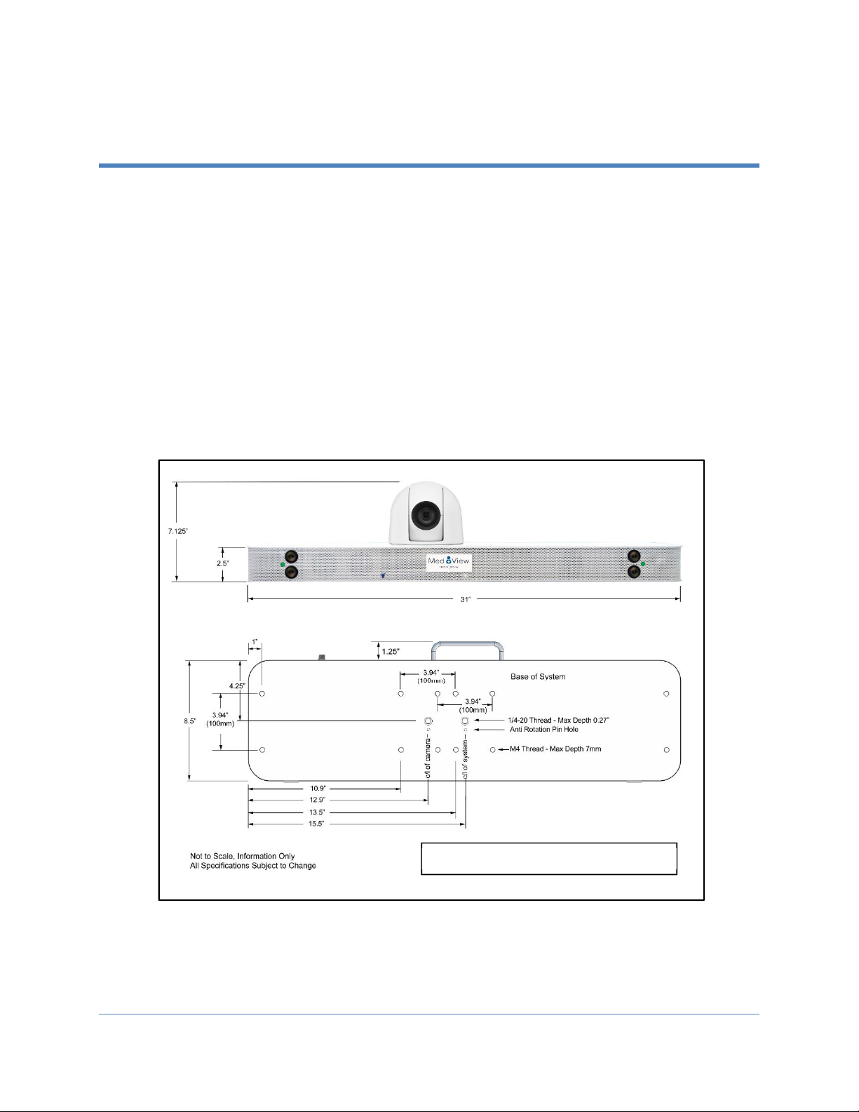
ceiling mounted. The diagram below shows the overall system dimensions plus the
mounting hole pattern in the base of the system. The basic mounting arrangement utilizes
standard 100mm x 100mm VESA compliant mounting holes, which are available in two
locations near the middle of the MedView. The first set of mounting holes is centrally
located (left to right) of the system, with a second set located directly below the camera.
These two mounting locations allow the system to be fitted directly above a monitor
where, either the system can be central to the display, or the camera can be central to the
display. In addition to the central VESA mounts, standard ¼ 20 mounting holes are also
centrally available in two locations, as well as mounting holes at the extreme edges for
custom mounting arrangements.
Please take careful note of the maximum thread depth available for the various mounting
point on the base of the MedView.
MedView System Weight: 17 pounds
Figure
3
.
MedView
S
ystem
Dimensions
Table of contents
Other Iron Bow Remote Control manuals