Inter-m PX-1650 User manual

PX-1650 Stereo Built In X-OVER
PX-1650_E 2003.9.8 10:42 AM 페이지2

Contents
Contents
1. Introduction/Unpacking and Installation .................................................................................1
2. Features ................................................................................................................................2
3. Precautions............................................................................................................................3
4. Front Panel Controls...............................................................................................................4
5. Top Panel Controls.................................................................................................................9
6. Rear Panel Controls .............................................................................................................12
7. Speaker Connections............................................................................................................14
8. Operating Tips.....................................................................................................................17
9. Applications ........................................................................................................................26
10. Block Diagram...................................................................................................................27
11. Specifications.....................................................................................................................28
OFFICE :
226-9 DUGJUNG - LI, HOE CHUN - EUB,
YANGJU - KUN, KYUNGKI - DO, KOREA
TEL : 82-351-860-7041~5, FAX : 82-351-858-1907
Home Page : http://www.inter-m.co.kr, http://www.inter-m.com
E-mail : [email protected]
PX-1650_E 2003.9.8 10:42 AM 페이지3

PX-1650 1
STEREO BUILT IN X-OVER
Introduction
Unpacking and Installation
Introduction
Thank you for purchasing a PX-1650 Stereo Quad Powered Mixer Built in X-OVER. The PX-1650 Series
provides an excellent balance of operability, functionally and ease of use. In order to take full advantage of
the PX-1650 Series capabilities and enjoy years of trouble-free use, please read this manual carefully.
Unpacking and Installation
Although it is neither complicated to install nor difficult to operate your set, a few minutes of your time is
required to read this manual for a properly wired installation and becoming familiar with its many features
and how to use them. Please take a great care in unpacking your set and do not discard the carton and
other packing materials. They may be needed when moving your set and are required if it ever becomes
necessary to return your set for service.
Never place the unit near radiators, in front of heating vents, to direct sun light, in excessive humid or dusty
location to avoid early damage and for your years of quality entertainment. Connect your complementary
components as illustrated in the following page.
RISK OF ELECTRIC SHOCK
DO NOT OPEN
CAUTION
CAUTION: TO REDUCE THE RISK OF ELECTRIC SHOCK.
DO NOT REMOVE COVER (OR BACK).
NO USER-SERVICEABLE PARTS INSIDE.
REFER SERVICING TO QUALIFIED SERVICE PERSONNEL.
WARNING
To prevent fire or shock hazard, do not
expose the unit to rain or moisture.
This symbol is intended to alert the user to the
presence of uninsulated “dangerous voltage”
within the product’s enclosure that may be of suf-
ficient magnitude to constitute a risk of electric
shock to persons.
This symbol is intended to alert the user to the
presence of important operation and mainte-
nance (servicing) instructions in the literature
accompanying the appliance.
Caution: To prevent electric shock do not use this (polarized) plug
with an extension cord, receptacle or other outlet unless
the blades can be fully inserted to prevent blade expo-
sure.
Attentions: Pour prévenir les chocs électriques ne pas utiliser cette
fiche polarisée avec un prolongateur, une prise de
courant on une autre sortie de courant, sauf si les
lames peuvent étre insérées à fond sans en laisser
aucune partie à découvert.
PX-1650_E 2003.9.8 10:42 AM 페이지4

PX-1650
2
STEREO BUILT IN X-OVER
Features
Features
- PX-1650 MONO INPUTS CHANNELS
The PX-1650 stereo quad powered mixer built in x-over provides 8, 12 channels of mono input that can be
mixed down to a stereo, 2 monitor, 2 EFFECT SEND output.
- XLR type connectors are provided for MIC jacks and 1/4” TRS connectors are provided for the LINE jacks.
- 2 STEREO CHANNELS
These mixing consoles provide 2 channels of stereo channel input that can be mixed down to a Stereo, 2
Monitor, 2 EFFECT sends out (MONITOR 1, 2 Per/EFFECT Send 1, 2 Post).
- 2 STEREO AUX RETURN
- 3 BAND EQ WITH SWEEPABLE MID-RANGE BAND
All mono input channels include 3 band EQ with sweepable mid-range frequency.
- INPUT CH INSERT I/O JACK
INPUT CH INSERT I/O jack is provided on each channel, allowing you to connect effect devices indepen-
dently for each channel.
- 7 BAND STEREO GRAPHIC EQUALIZER
Frequency Band: 63, 160, 400, 1k, 2.5k, 6.4k, 15kHz.
- 16 x 16 PROGRAMMABLE DSP
- 4 CHANNEL STEREO POWER AMP
250W×4, 4Ωat THD 0.1%.
PX-1650_E 2003.9.8 10:42 AM 페이지5

3
PX-1650
Precautions
Precautions
- AVOID EXCESSIVE HEAT, HUMIDITY, DUST AND VIBRATION
Keep the unit away from locations where it is likely to be exposed to high temperatures or humidity-such as
near radiators, stoves, etc. Also avoid locations which are subject to excessive dust accumulation or vibra-
tion which could cause mechanical damage.
- VENTILATION
The unit has ventilation slots on the side and bottom panels. Do not block these vents.
- AVOID PHYSICAL SHOCKS
Strong physical shocks to the unit can cause damage. Handle it with care.
- DO NOT OPEN THE CASE OR ATTEMPT REPAIRS OR MODIFICATIONS YOURSELF
This product contains no user-serviceable parts. Refer all maintenance to qualified Inter-M service person-
nel. Opening the case and/or tampering with internal circuitry voids the warranty.
- ALWAYS POWER OFF BEFORE MAKING CONNECTIONS
Always turn the power OFF before connecting or disconnecting cables. This is important to prevent damage
to the unit itself as well as other connected equipment.
- HANDLE CABLES CAREFULLY
Always plug and unplug cables-including the AC power cord-by gripping the connector, not the cord.
- CLEAN WITH A SOFT DRY CLOTH
Never use solvents such as benzine or thinner to clean the unit. Wipe clean with a soft, dry cloth.
STEREO BUILT IN X-OVER
PX-1650_E 2003.9.8 10:42 AM 페이지6

4PX-1650
STEREO BUILT IN X-OVER
Front Panel Controls
1. MONO INPUT SECTION
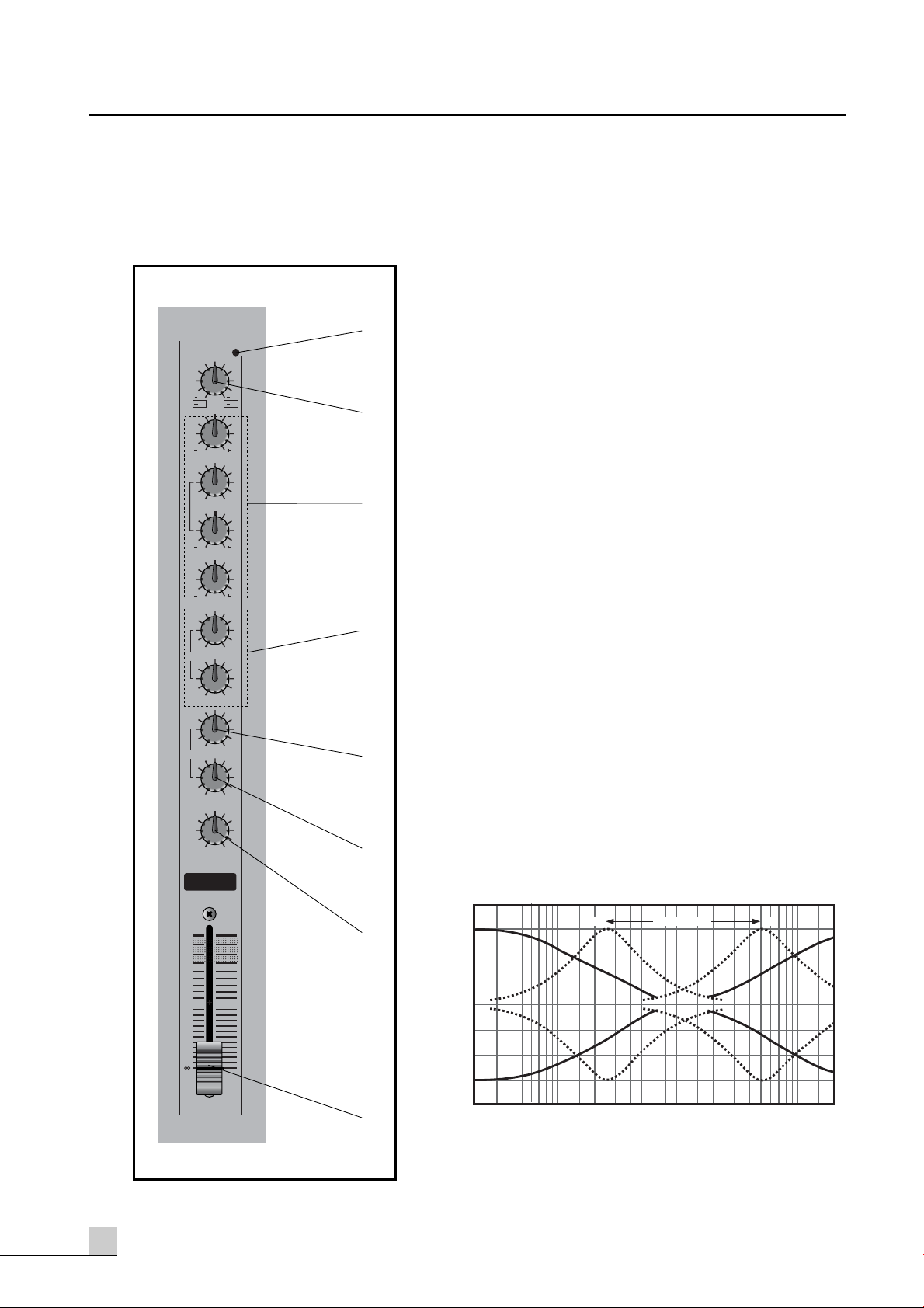
1. PEAK LED INDICATORS
This LED indicators let you check the level of the signal
input to the channel.
The peak indicator lights when the input signal reaches
3dB below the channel’s clipping point.
This indicator show the level of the post-EQ/pre-fader
signal. If the PEAK indicator lights more than briefly on
high-level transients, you should use the GAIN control to
decrease the input sensitivity of the channel. If this dose
not work, reduce the output level of the connected source.
2. GAIN CONTROL
This control adjusts the channel’s mic input sensitivity
between -60dB and -16dB and the line input sensitivity
between -30dB and +14dB. Continuously variable gain
control allows optimum adjustment to virtually any micro-
phone or line source.
3. EQUALIZER CONTROLS
This set of four controls allows you to individually modify
the channel’s response. Each channel of the PX-1650 is
equipped with a 3 band equalizer (EQ) that has shelving
HIGH and LOW controls, and a peaking MID control
with a sweepable center frequency (which is adjusted by
the MID FREQ control). Refer to “Using the Channel
Equalizers” on page 14 for details on the use of these
controls.
HIGH: 12kHz, ±15dB shelving type
MID: 250Hz~5kHz, ±15dB peaking type
LOW: 80Hz, ±15dB shelving type
1
0
20
25
30
35
40
10
15
5
PAN
LR
PEAK
EFX
010
EFX 1
010
EFX 2/REV
LOW
15 15
5250 FREQ
MID
15 15
HIGH
15 15
TRIM 60
30
14
16
010
MON
010
1
2
3
4
5
6
7
8
MON 1
MON 2
+20
+15
+10
+5
0
-5
-10
-15
-2020 50 100 200 500 1k 2k 5k 10k 20k
FREQUENCY (Hz)
RESPONSE (dB)
250 MID FREQ 5k
PX-1650_E 2003.9.8 10:42 AM 페이지7

5
PX-1650
4. MONITOR 1 AND 2 CONTROL
These control determines the level of the post-EQ/pre-fader signal that is sent from the channel to the
monitor mixing buses. All signal sent to the Monitor bus are mixed, then fed to the Monitor 1 and 2
Jacks on the top panel after their final output levels have been set by the Monitor 1 and 2 controls in the
Master control section.
5. EFFECT 1 CONTROL
This control determines the level of the post-EQ/post-fader signal that is sent from the channel to the
Effect 1 mixing bus. The channel signals mixed by this bus have their overall level set by the EFFECT
SEND 1 Control. Then are sent to the EFFECT SEND 1 jack. The output from this jack can be
processed by an external effect device.
6. EFFECT 2 CONTROL
This control determines the level of the post-EQ/post-fader signal that is sent from the channel to the
Effect 2 mixing bus. The channel signals mixed by this bus are sent via the EFFECT SEND 2 Control to
the EFFECT SEND 2 jack on the top panel. The output signal is also fed into the PX-1650 internal
digital signal processor. Thus, a signal fed to the Effect 2 bus using this control can be processed
externally or internally.
7. PAN CONTROL
This control pans the channel signal across the master L and R buses, thus determining the perceived
position of the sound from that channel in the output stereo sound field. If a PAN control is set all the
way to the left, for example, the sound from that channel will be heard from the left speaker system only.
If it is set all the way to the right, the sound will be heard from the right speaker system only.
Intermediate settings will cause the sound to appear at corresponding locations in the stereo sound field.
8. CHANNEL FADER
This is the channel’s main level control. It determines the level of the signal that is sent from the channel
to the master mixing and effect buses. It is the settings of the input channel faders that determine the
“mix”, or the balance of sound levels between the instruments or other sources connected to the inputs.
When a channel is not being used, its fader should be set at the minimum position to prevent the
addition of unwanted noise to the main program signal.
STEREO BUILT IN X-OVER
PX-1650_E 2003.9.8 10:42 AM 페이지8

6PX-1650
2. STEREO INPUT SECTION
1. PEAK LED INDICATORS
This LED indicators let you check the level of the signal
input to the channel.
The peak indicator lights when the input signal reaches
3dB below the channel’s clipping point.
This indicator show the level of the post-EQ/pre-fader
signal. If the PEAK indicator lights more than briefly on
high-level transients, you should use the GAIN control to
decrease the input sensitivity of the channel. If this dose
not work, reduce the output level of the connected source.
2. GAIN CONTROL
This control adjusts the stereo channel’s input sensitivity
between -20dB and +14dB. Continuously variable gain
control allows optimum adjustment to virtually any line
source.
3. EQUALIZER CONTROLS
This set of three controls allows you to individually
modify the stereo input response. Stereo channel of the
PX-1650 is equipped with the 3 band equalizer (EQ) that
has shelving HIGH, LOW, and Peaking MID controls.
Frequency response will be flat when the knob is center
position.
Will be flat when the knob is center position.
HIGH: 12kHz, ±15dB shelving type
MID: 2.5kHz, ±15dB peaking type
LOW: 80Hz, ±15dB shelving type
4~8. Please refer to Mono Input Section No. 4~8.
STEREO BUILT IN X-OVER
13/14
0
20
25
30
35
40
10
15
5
010
MON 2
PEAK
TRIM 20
LOW
15 15
MID
15 15
HIG
15 15
010
EFX 2/REV
01
EFX 1
EFX
BALANC
LR
MON
010
MON 1
14
1
2
3
4
5
6
7
8
+20
+15
+10
+5
0
-5
-10
-15
-2020 50 100 200 500 1k 2k 5k 10k 20k
FREQUENCY (Hz)
RESPONSE (dB)
PX-1650_E 2003.9.8 10:42 AM 페이지9

7
PX-1650
3. MASTER SECTION
1. OUTPUT LEVEL METER
A vertical row of ten LED show the continuous output lev-
el of main Output L/R or monitor 1/2 by signal select
switch. This type of display is free from over shoot prob-
lem of mechanical meters and is highly visible under
poor lighting conditions.
The 0 LED means an output level of +4dB for +4dB out-
put (that’s the rated level).
2. SIGNAL SELECT SWITCH
This switch is used to select which signals are displayed
the following table shows how they work.
You can select main L/R or monitor 1/2 signal to Amp
Output and Headphone Output.
3. DIGITAL EFFECT SECTION
This section lets you control the PX-1650 Series internal
digital signal processor (DSP).
The bank of LED indicators at the top of the section show
the current DSP program selection, which is changed
using the PROGRAM control.
Determines the application parameter of the selected program for each program 16 different parameter
are available. Refer to “Using the Digital Signal Processor” on page 15 for details on the use of this section.
4. STEREO GRAPHIC EQUALIZER SECTION
The PX-1650 Series internal stereo graphic equalizer (GEQ) allows the fine response shaping of the
main program output. This section has seven linear controls, corresponding to center frequencies of
63Hz, 160Hz, 400Hz, 1kHz, 2.5kHz, 6.4kHz, 15kHz. Each control permits a maximum boost or cut of
12dB. When a control is set to the center or “0” position, the response in the corresponding band is
unaffected. The EQ switch turns the graphic equalizer on and off.
5. EFFECT RETURN CONTROLS
These controls adjust the levels of the signals that are received at the corresponding EFFECT RETURN jacks
on the top panel (or from the internal digital signal processor, when the DSP is used in place of external
input to the EFFECT RETURN 2 jacks). Each effect return circuit has two controls. The EFX 1, EFX 2 level
control adjusts the level of the signal that is mixed into the main program on the master mixing bus. The
EFX 1 to MON 1 control set the level of the signal that is mixed into monitor 1 bus, where it is mixed
with other signal for output by the monitor/out jacks on the top panel. The EFX 2 to MON 2 control used
same function as EFX 1 to MON 1 control but this control offer to DSP output signal, when you turn on
the DSP.
STEREO BUILT IN X-OVER
Meters Switch Up Switch Down
L/Monitor 1 Main L Output Monitor 1 Output
R/Monitor 2 Main R Output Monitor 2 Output
Output Switch Up Switch Down
Amp & Headphone Main L/R Monitor 1/2
PX-1650_E 2003.9.8 10:42 AM 페이지10

8PX-1650
6. MONITOR 1, 2 OUTPUT CONTROL
These controls adjust the overall output levels of the monitor mix that are setup using the monitor control
of each channel. The Monitor 1 or Monitor 2 mix signal are sent to the monitor output 1 and monitor out
2 jacks on the top panel. These controls should be used to optimally match the monitor mix output levels
to the input sensitivities of the power amplifiers used.
7. EFFECT SEND CONTROLS
These Control, adjust the overall output levels of the effect mixes that are set up using the EFFECT 1 and
EFFECT 2 controls of each input channel. The EFFECT SEND 1 Control sets the overall level of the signal
that appears at the EFFECT SEND 1 jack on the top panel. The EFFECT SEND 2 Control sets the overall
level of the Effect 2 mix signal, which is sent to both the EFFECT SEND 2 jack on the top panel and the
internal digital signal processor. These Control should be used to optimally match the effect mix output
levels to the input sensitivities of the effect signal processors used.
8. REC OUT AND TAPE IN CONTROLS
These controls adjust the levels of the stereo signals to and from a connected tape deck. The REC OUT
control sets the level of the unequalized pre-fader master mix signal that is sent for recording by the tape
deck via the REC OUT jacks on the top panel. The TAPE IN control adjusts the level of the playback
signal that is inserted to the master mixing bus from the TAPE IN jacks on the top panel. This playback
signal is added to the bus in front of GEQ, allowing the PX-1650 to equalizer the signal from the tape
deck before output.
9. PHONES CONTROL
This control adjusts the level of the stereo signal delivered from the PHONES jack located directly below
it on the front panel. Since this level adjustment is made after the GEQ, the volume of sound heard from
the headphones will be affected by both the master stereo faders and the PHONES control.
10. PHONES JACK
This jack delivers the main program signal to a pair of 40Ωstereo monitor headphones. The volume of
the output signal is adjusted by both the PHONES control and the master stereo faders.
11. MONO OUTPUT FADER
This fader adjusts the final level of the combined stereo signal and send the mono output jacks.
12. MASTER STEREO FADERS
These are the main volume controls for the overall program mix. They independently adjust the levels of
the right and left channels of the stereo signal that is sent to both the rear-panel SPEAKER jacks and the
GEQ PHONES jack on the front panel.
STEREO BUILT IN X-OVER
PX-1650_E 2003.9.8 10:42 AM 페이지11
Table of contents
Other Inter-m Dj Equipment manuals