Intelligent Cleaning Equipment iP17 Programming manual

Operator & Parts Manual
175 RPM Floor Machine
wwwicecompanies.com
4310403
REV.01(01-2019)
iP17
iP20
INTELLIGENT CLEANING EQUIPMENT

HOW TO ORDER PARTS
Only use ICE Company supplied or equivalent parts. Parts and supplies may be ordered
online,by phone, by fax or by mail.
1. Identify the machine model.
2. Identify the machine serial number from the data label.
3. Ensure the proper serial number is used from the parts list.
4. Identify the part number and quantity.
Do not order by page or reference numbers.
5. Provide your name, company name, customer ID number,billing and shipping address,
phone number and purchase order number.
Please ll out at time of installation for future reference.
Model No.
Serial No.
Machine Options
Sales Rep.
Sales Rep. phone no.
Customer ID Number
Installation Date
READ OPERATOR MANUAL CAREFULLY
ICE Company Limited
XiangShi Road LiaoBu DongGuan GuangDong China
Tel:0769-8186 9000
Fax:0769-8186 3000
Specifications and parts are subject to change without notice.
PROTECT THE ENVIRONMENT
Please dispose of packaging materials,old machine components
such as batteries,
hazardous uids, including antifreeze and oil, in an environmentally
safe way according to local waste disposal regulations.
Always remember to recycle.
ICE iP17 iP20
2
IMPORTANT:To ensure full warranty protection,Please ll out
& return your warranty card.

SAFETY PRECAUTIONS . . . . . . . . . . . . . . . . . . . . . . . . . . . . . . 4
MACHINE COMPONENTS . . . . . . . . . . . . . . . . . . . . . . . . . . . . . 5
MACHINE OPERATING INSTRUCTIONS . . . . . . . . . . . . . . . . . .6
MACHINE MAINTENANCE & STORAGE . . . . . . . . . . . . . . . . . . 6
HANDLE RELEASE ASSEMBLY INSTRUCTIONS . . . . . . . . . . . 7
PARTS LIST . . . . . . . . . . . . . . . . . . . . . . . . . . . . . . . . . . . . . . 8-13
WEAR & TEAR PARTS LIST . . . . . . . . . . . . . . . . . . . . . . . . . . . .13
SOLUTION TANK ASSEMBLY(OPYIONAL ) . . . . . . . . . . . . .14-15
SPECIFICATIONS . . . . . . . . . . . . . . . . . . . . . . . . . . . . . . . . . . . 16
WIRING DIAGRAM . . . . . . . . . . . . . . . . . . . . . . . . . . . . . . . . . . 16
ICE iP17 iP20 3
TABLE OF CONTENTS

SAFETY PRECAUTIONS
ICE iP17 iP20
4
OPERATOR
Carefully read and understand this manual before operating this machine.
This machine must be grounded!
This oor/nishing machine shall be grounded while in use to protect theoperator from electric
shock.Grounding provides a path of least resistance for electric current. This machine is
equipped with a cord having an equipment-grounding conductor and grounding plug. The plug
must be plugged into an appropriate outlet that is properly installed and grounded in accordance
with all local codes and ordinances. Do not remove the ground pin under any circumstances.
This machine is for use on a nominal 120-volt circuit
and has a grounding plug that resembles the plug
illustrated in Figure. Make sure that the machine is
connected to an outlet having the same conguration as
the plug. No adapter should be used with this machine.
This machine is intended for commercial use. It is constructed for use in an indoor environment
and is nor intended for any other use. Use only recommended accessories.
1. Do not operate machine:
– Unless trained and authorized. – Unless you have read and
– In ammable or explosive areas. understand the operators manual.
– With a damaged cord or plug – With the use of extension cords.
– If not in proper operating condition. – In outdoor areas and standing water.
2. Before operating machine:
– Make sure all safety devices are in place and operating properly.
3. When using machine:
– Do not run machine over cord. – Do not pull machine by cord or plug.
– Do not pull cord around – Do not unplug by pulling on the cord.
sharp edges or corners. – Do not stretch cord.
– Do not handle plug with wet hands. – Keep cord away from heated surfaces.
– Report machine damage or faulty
operation immediately.
To avoid electrical shock,please replace the power cord immediately if any damage is
being detected. The replacement must be performed only by an authorized person or
by our customer service center.
4. Before leaving or servicing machine:
– Turn off machine. – Unplug cord from outlet.
5. When servicing machine:
– Unplug cord from outlet. – Use manufacturer supplied or
approved replacement parts.
When moving, repairing and tilting the machine, make sure the safety
installation is right place and tighten the release handle.

MACHINE COMPONENTS
ICE iP17 iP20 5
OPERATOR
Machine Description
• New structure design
• 17" 0r 20" Deck alumiunm
• 16" or 19" Pad Driver
• Triple Planetary All Steel Gear Box
• Universal Clutch Plate
• Safety Lock-Out Switch
• Security protection in an upright
• 50' Cord
• 66-Frame Motor
Machine Structure
1. Deck 2. Wheel
3. Safety installation 4. Level Solution
5. Trigger 6. Safety Lock-Out Switch
7. Housing 8. Handle Release Assy
9. Top Cover 10. Motor
2
3
5
1
4
6
7
8
9
10
11
11.Clutch Plate

FLOOR MACHINE OPERATING INSTRUCTIONS
6
OPERATOR
General Use:
1) Remove any obstructions or other obstacles in the area which is to be cleaned.
2) Make sure the safety installation is right place and tighten the release handle.
3) Place handle in upright position and tilt machine back until handle rests on the oor.
Be sure the machine is not plugged into an outlet.
8) Release the compression handle and adjust handle height to a comfortable operating position,
then push back down on the compression handle to lock the handle in operating position.
9)To start the machine, push on the Blue safety button of the top of upper switch housing and
squeeze either of the switch levers.
10) When the machine is in operation, both hands should be placed on the handle (switch
housing).
11)To stop the machine at any time, simply release the switch lever, and the machine will stop
automatically.
Do not use an extension cord in conjunction with the standard power cord.
4) Remove the pad center gripping device by unscrewing the thumbscrews.
5) Place appropriate burnishing pad on pad driver and re-attach the center gripping device.
6) Place machine back into its upright position.
7) Plug power cord into grounded outlet.
STORAGE
1) Unplug machine from power source and wrap cord on handle.
2) Tilt machine back and remove pad driver or brush.
3) Store in upright position in a dry area.
MAINTENANCE
To keep the machine performing well for many years, please follow the following maintenance
procedures.
Always confirm that the machine is unplugged prior to performing any
maintenance or repairs.
1. Unplug machine as soon as you are done using it.
2. Make sure the safety installation is right place and tighten the release handle.
3. Tilt machine back and remove pad driver or brush.
Never store a low speed machine with the pad driver or brush mounted
to the machine.
4. Clean the outside of the machine with a mild cleaner.
5. Check power cord for any damage.If damage is detected, replacepower cord immediately.
6. Lubricate wheels with a water resistant lubricant once a month.
7. Check machine for loose or missing nuts and bolts, and replace as necessary.
8. If the machine is used in a dusty environment, you may remove themotor cover and blow the
motor clean with compressed air. This willensure proper ventilation, and allowthe motor to run
cooler.
ICE iP17 iP20

ICE iP17 iP20
7
OPERATOR
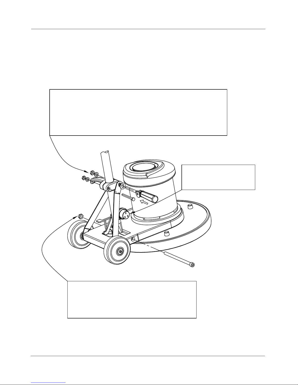
HANDLERELEASE ASSEMBLYINSTRUCTIONS
1)Assemblehandleand handlereleaseassembly: According tointhe following
photos direction assembly.
Step 2
1)Takeout the handleassembly, nut lock M12,
hex. socket head M12x210.
Step 1
2)After Aligning them, and usespanner totighten them.
2)Adjust the nylon lock nut: It don't over tighten nylon lock nut, only tighten it
enough toholdhandleinplacewhen compression lever is indown position.
Step3
1)Connect power cords together

iP17 &iP20 HANDLEASSEMBLY
PARTS LIST
ICE iP17 iP20 8
PARTS LIST

ICE iP17 iP20
9
DIA
NO PART
NUMBER NO
REQ'D
1 1021855 1
2 4313113 1
3 4310120 1
4 1123012 1
5 1421020 1
6 1123810 2
7 1421816 1
8 4313101 1
9 4010403 2
10 1511540 2
11 4010320 1
12 1434500 4
13 1211512 4
14 1221412 1
15 4020310 1
16 1434400 2
17 4010314 3
18 40103311
19
4010305
1
PIN
iP17 & iP20 HANDLE ASSEMBLY
DESCRIPTION
SCREWM8X55
BRACKET
TUBING
NUTLOCK M10
WASHER PLAIN 10.5X 20X2
NUTLOCK M8
WASHER PLAIN 8X 16.5X1.0
HOOK CABLE
CLAMP TANK
SCREWM5 X40 HEXSOCKET
CORD POWER SUPPLY
TOOTH WASHER 5
SCREWM5X12
SCREWM4X12
STRAIN RELIEF CORD
TOOTH WASHER 4
LEFTTRIGGER SWITCH
19
4010305
1
20 4010312 1
21 1421616 4
22 1512635 2
23 1512625 2
4020105 1
4010313U 1
25 5013009 1
26 4310008 1
27 4010317 1
28 1211408 2
29 40103301
30 1211325 2
31 1434300 2
32 4010323 1
33 4010308 1
34 4010307 1
35 4010333 1
36 4010301 1
37 4010316 1
38 4010311 1
SAFETYSPRING
24
REAR COVER
WASHER PLAIN 6
SCREWM6 X35
SCREWM6 X25
SERIAL NUMBER[iP17]
LEVEL SOLUSOLUTION
SCREWM3X25
TOOTH WASHER
SPRING SAFETY
SWITCH
SAFETYBOTTOM
SERIAL NUMBER[iP20]
COVER
BALL BASE
SCREWM4X8
RIGHTTRIGGER SWITCH
CIRCUITBREAKER 20A
FRONTCOVER
ICE LOGO
CLAMP CORE

ICE iP17 iP20 10
39 1221406 2
40 1031860 1
41 4313111 1
42 1647825 1
43 4313104 1
44 4313103 1
45 4313102 1
46 4010215 1
47 4010120 1
48 4010213 1
49 6311003 2
iP17 & iP20 HANDLE ASSEMBLY
SCREWM8X60
HANDLE RELEASE
PIN Ø8X25
SCREWM4X6
GROMMET
WASHER NYLON PLAIN 8
VOLTHANDLE RELEASE
WASHER PLAIN HANDLE RELEASE
COVER HOOK HANDLE
CORD HANDLE
PLUG PROTECTOR COVER
This manual suits for next models
1
Table of contents