Infinite Play ipdoor Flush User manual

Quick Start
Guida Rapida
A New Interactive Experience

)OXVK 7RXFK
130mm 95mm 20mm2mm
25mm
42mm
262mm
311mm
Wall
Per registrare la targa in una rete wireless, premere a lungo nella parte
alta dello schermo, accedere alle impostazioni di rete, selezionare la
propria rete tra quelle disponibili ed inserire i dati di accesso.
To register the door station in a wireless network, long press at the top of
the screen, access the network settings, select your network from those
available and enter the access data.
&RQƪJXUD]LRQH:,),
:,),&RQƪJXUDWLRQ
90°
-90°
0°
180°
45°315°
270° 90°
225° 135°
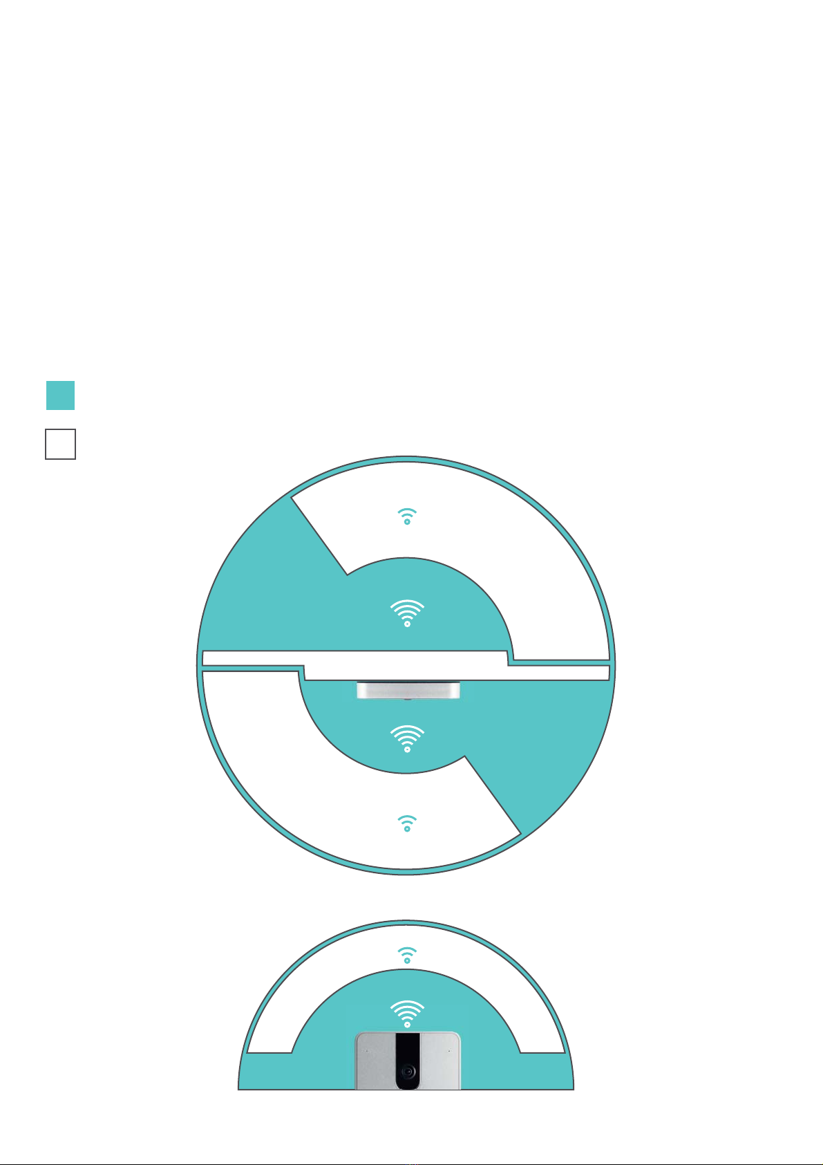
Vista dall’alto
Top View
Area a bassa copertura
Low coverage area
Area ad alta copertura
High coverage area
Vista Frontale
Front View
2
0
m
1
0
m
1
5
m
1
0
m
Per ottenere prestazioni migliori posizionare la targa nell’area ad alta copertura.
For best performance, place the door station in the high coverage area.

&ROOHJDPHQWR,QJUHVVL$OODUPH
Connection of Alarm Inputs
M
Ingresso generico
Generic input
Pulsante esterno apriporta
External door button
IN2IN1
L
Gli ingressi “IN1” e “IN2” vanno riferiti alla massa “M”.
Per aggiungere un pulsante apriporta esterno, collegare il pulsante
WUDLPRUVHWWL,1R,1H0HGDVVRFLDUHOoLQJUHVVRVFHOWRDOOoD]LRQH
uscita OUTPUT nelle impostazioni della targa.
The inputs “IN1” and “IN2” must refer to ground “M”.
To add an external door opener button, connect the button between termi-
nals IN1 (or IN2) and M and associate the chosen input with the OUTPUT
output action in the door station settings.

0RUVHWWLH&RQQHWWRUL
Terminals and Connectors
24V @ 0,5A
RS485 -
IN1
AUX1
Lock+
M
RS485 +
IN2
AUX1
Lock-
B
OI O GI B BI G BrlBr Rj-45 Plug
RJ-45 EIA/TIA 568B CAT5/6
Presa di rete/ Network Socket
Scheda rete/ Network Card :
10/100Mbps PoE IEEE 802.3af.
A
51mm
Made in italy
A Porta Ethernet
Ethernet port
B Morsetto estraibile a 10 poli
Removable 10-pole terminal
C
Ripristino impostazioni di
fabbrica
Premere per 10 secondi al riavvio
Factory reset
Hold for 10 seconds on reboot
51mm

&ROOHJDPHQWR(OHWWURVHUUDWXUD
Electric Lock Connection
La targa dispone di un’uscita alimentata 9$ per l’azionamento
di una serratura elettrica senza l’ausilio di un alimentatore
supplementare. La serratura va connessa, seguendo lo schema del
produttore, ai morsetti “/2&.” e “/2&.” rispettivamente positivo
9HQHJDWLYRPDVVDFRQXQFDYRHOHWWULFRGLOXQJKH]]DPDVVL
PD PHWUL e VH]LRQHPLQLPDPP
The door station has a 12V 1A powered output for the drive of an
electric lock without the aid of an additional power supply. The locks must
be connected, following the manufacturer’s scheme, to the terminals
“LOCK +” and “LOCK-” respectively positive (+ 12V ) and negative (earth)
with an electric cable with a maximum length of 50 meters and minimum
section 1,5mm.
Max 50m - sez. min. 1,5mm
12V @1A
LOCK+ LOCK-
L
2

Utilizzare un alimentatore stabilizzato 24V @0.5A tipo ICA0001.
Facendo riferimento all’uscita 24V dell’alimentatore, collegare il
positivo all’ingresso 24V @0,5A ed il negativo all’ingresso M sui
morsetti della targa.
Use a 24V @0.5A stabilized power supply like ICA0001. Referring to
the 24V output of the power supply, connect the positive to the 24V
@0.5A input and the negative to the M input on the door station clamps.
&ROOHJDPHQWR$OLPHQWDWRUH(VWHUQR
External Power Supply Connection
85~ 264 V
24V
24V @0,5A M
INPUT
OUTPUT
L
,&$
NL
v+
+
v-
-
NL

,PRUVHWWL$8;LGHQWLƪFDQRXQoXVFLWDUHOÃ1$FRQFDULFRPDVVLPR
supportato di 1A@24V o 1A@24V .
The AUX1 terminals identify a relay output (NO) with a maximum suppor-
ted load of 1A@24V or 1A@24V .
&ROOHJDPHQWR8VFLWD5HOÃ
Relay Output Connection
Alimentatore
Power Supply
L
AUX1 220V
AUX1
AUX1AUX1
Max 24V @1A
Max 24V @1A
o
Alimentatore
Power Supply
Schema di collegamento diretto
Direct connection diagram
6FKHPDGLFROOHJDPHQWRWUDPLWHUHOÃGLSRWHQ]D
Connection diagram via power relay
Max 24V @1A
Max 24V @1A
o

/oLQVWDOOD]LRQHZLUHOHVVVLUHDOL]]DFRQQHWWHQGRODVFKHGD:LƪD*K]
integrata ad un access point o router wireless. Questo tipo di collega-
mento prevede l’utilizzo di un alimentatore esterno 24V tipo ICA0001
da collegare direttamente alla targa.
The wireless installation is made connecting WKHLQWHJUDWHG*K]:LƪFDUG
to a wireless access point or router. This type of connection requires the use
of an external 24V power supply like ICA0001 to be connected directly to
the door station.
Schema con collegamento di rete wireless ed alimentatore esterno
Diagram with wireless network connection and external power supply
,QVWDOOD]LRQH:,),
WI-FI Installation
CAT 5/6
3689
Door Station
Internal Units
Smartphone
WI-FI
WI-FI Router Cloud
th

L’installazione LAN si realizza collegando un cavo di rete CAT5/6 tra la
VFKHGDGLUHWHSRVWDVXO UHWUR GHOOD WDUJDHGLOURXWHURXQRVZLWFK
Questo tipo di collegamento prevede l’utilizzo di un alimentatore ester-
no 24V tipo ICA0001 da collegare direttamente alla targa.
The LAN installation is made connecting a CAT5/6 network cable between
the network card, located on the back of the door station, and the router (or
switch). This type of connection requires the use of an external 24V power
supply like ICA0001 to be connected directly to the door station.
Schema di collegamento con cavo di rete CAT5/6 ed alimentatore esterno
Connection diagram with CAT5/6 network cable and external power supply
,QVWDOOD]LRQH/$1
LAN Installation
CAT 5/6
max 100m
3689
Door Station
Internal Units
Smartphone
WI-FI
Router Cloud
th
CAT 5/6
This manual suits for next models
1
Table of contents