Indu-Sol PROFInet-INspektor User manual

Diagnostic and service tools for PROFINET
Your partner and specialist for field bus systems, Industrial Ethernet and PROFINET
PROFInet-INspektor®
MANUAL
Indu-Sol GmbH • Blumenstrasse 3 • D - 04626 Schmoelln • Germany
Telephone: +49 34491 5818-0 • Fax: +49 34491 5818-99 • E-Mail: info@indu-sol.com • www.indu-sol.com


List of revisions
Date Revision Change(s)
08/06./2011
0 First version
25/10/2011 1 Revised version
05.02.2012 2 Revised version
04.04.2012 3 Revised version
27.08.2012 4 Revised version
© Copyright 2011 Indu-Sol GmbH
We reserve the right to make changes without prior announcement. Our
products are subject to constant improvement. We also reserve the right to
change the scope of supply as regards form, configuration and equipment.
No claims can be derived from the data, figures and descriptions of this
documentation. Any reproduction, processing and translation of this
document or any extract thereof are subject to written approval by Indu-Sol
GmbH. All rights pursuant to the copyright law shall be expressly reserved
to Indu-Sol GmbH.
Attention!
This device may only be started and operated by qualified personnel.
Qualified personnel within the meaning of the safety information
contained in this manual are persons who are authorized to start, ground
and mark devices, systems and circuits in accordance with the safety
standards. .

Table of contents
1 General 6
1.1
Scope of supply 6
1.2
Safety information 6
1.3
Purpose of use 6
2 Installation 7
2.1
Connecting the voltage supply 7
2.2
Connecting to PROFINET 7
3 Electrical connections 8
3.1
Voltage supply 9
3.2
Web interface 9
3.3
COM 10
3.4
Mirror Port 12
3.5
NETWORK IN 12
3.6
NETWORK OUT 12
3.7
RESET button 12
3.8
LED functions 13
3.8.1
PWR 13
3.8.2
LAN 13
3.8.3
RUN 13
3.8.4
ERROR 13
3.8.5
ALARM 13
4 Web interface 14
4.1
Display of web interface 14
4.2
Parameters of web interface 15

4.2.1
External diagnosis 15
4.2.2
Internal diagnosis 15
4.2.3
Utilization 15
4.2.4
Data throughput 15
4.2.5
Refresh rates – telegram jitter 16
4.2.6
Connection attempts 16
4.2.7
Error telegrams 16
4.2.8
Package types 16
4.3
The network statistics 17
4.4
Buttons and possible settings 17
4.4.1
Buttons on start page 18
4.4.2
Threshold values and alarms 19
4.4.3
Last cycle 19
4.4.4
Designation of subscribers 19
4.4.5
System settings 20
5 Technical data 21
6 CE Declaration of Conformity 22
7 Notes 24

General
sh. 6 of 26
1 General
Read the entire content of this document carefully before you install
and start up this device.
1.1 Scope of supply
The following components: are included in the delivery:
•PROFInet-INspektor
®
- PIT hardware
•24V voltage supply connector
•Software CD
•Installation manual
Check for completeness prior to start-up.
1.2 Safety information
Never open the housing of the PROFInet-INspektor
®
.
If the device is assumed to be defective, send it back to the supplier.
Warranty will expire immediately if the housing is opened.
1.3 Purpose of use
The PROFInet-INspektor
®
is designed to permanently monitor the
PROFINET in automation systems.
Never use the device in explosion-hazardous areas.

Installation
sh. 7 of 26
2 Installation
The PROFInet-INspektor
®
is snapped horizontally onto a TS35 DIN
mounting rail in the switchgear cabinet.
The PROFInet-INspektor
®
is cooled conventionally by heat exchange
with the ambient air.
When installing the device make sure that the venting slots of the
device are not obstructed by other components. An all round
distance of 30 mm to other devices should be ensured.
2.1
Connecting the voltage supply
Provide the PROFInet-INspektor
®
with the necessary voltage of 24
V DC, Observe the polarity. The PE terminal can be used as
protective earth.
2.2
Connecting to PROFINET
Now, that the voltage supply has been connected you have to
connect the PROFInet-INspektor
®
with the PROFINET. To this end
connect the outgoing line of the controller with the "Network IN"
interface and route the "Network OUT“ interface to the other field
devices..
If the device is connected via an ETMA (TAP) , keep in mind that the
incoming line needs to be a crossover cable because otherwise the
internal pair allocation of the interfaces will be incorrect and the
analysis cannot be started.
The PROFINET-INspektor
®
starts automatically analysing the
PROFINET data traffic.
Device names will only be recognized in the run-up phase of the
PROFINET, however.
Electrical connections
sh. 8 of 26
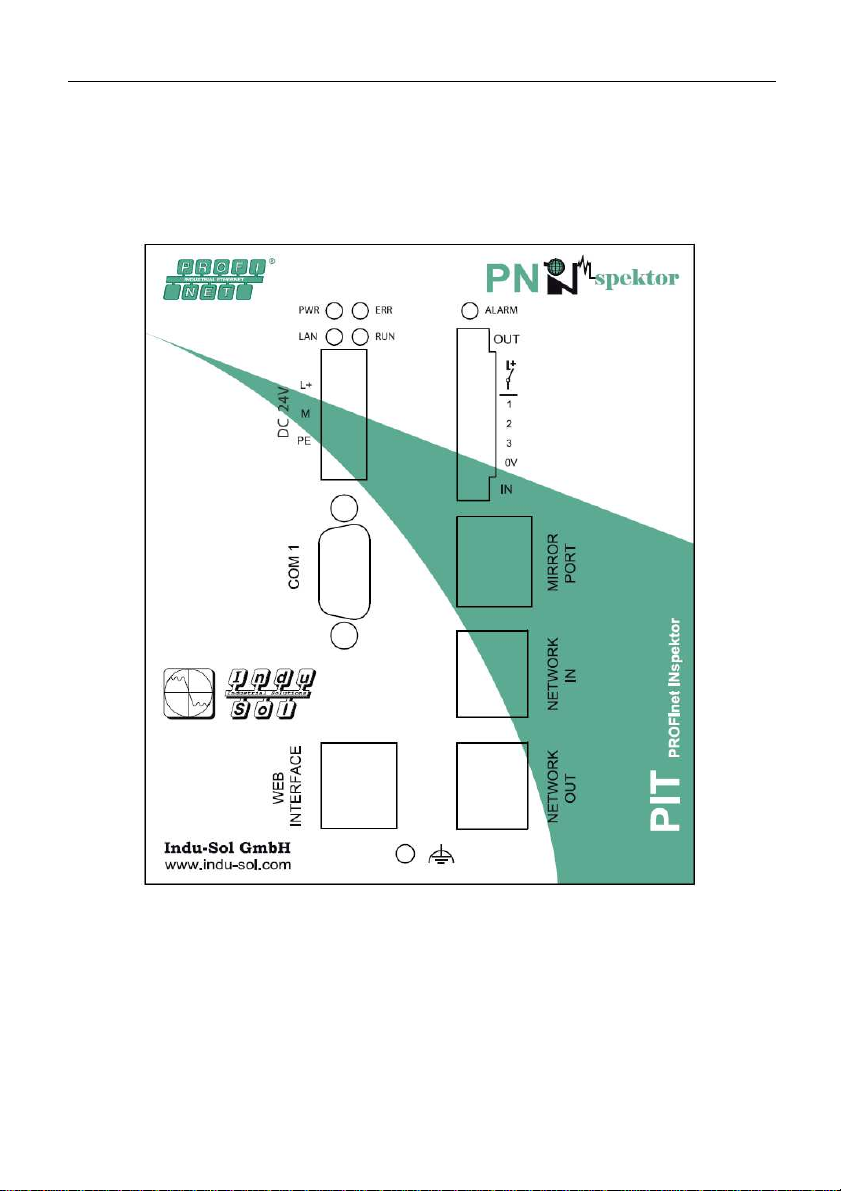
3 Electrical connections
Fig. 1 is a schematic representation of the PROFInet-INspektor
®
Fig. 1: Front view of the PROFInet-INspektor
®

Electrical connections
sh. 9 of 26
3.1 Voltage supply
The PROFInet-INspektor
®
is supplied with 24V DC. The required
terminal strip is included in the scope of supply. The voltage supply
connection is shown in Fig. 1 as "DC 24V".
The L+ terminal is supplied with +24V and the M terminal with 0 V.
It is also necessary to provide a PE connection. Where a strong
electromagnetic radiation is present in the environment of the
PROFInet-INspektor
®
the earthing screw under the web interface
port should be additionally connected.
The voltage supply cables should have a minimum cross section of
0.75mm² and max.1.5mm².
The PROFInet-INspektor
®
has an internal overvoltage protection.
The latter triggers at voltages above 30 V and can be replaced by
Indu-Sol GmbH only.
IMPORTANT:
Under normal operating conditions the PROFInet INspektor
®
has a
power consumption of 500mA. In the starting phase, however, 3 A
will be needed for a short period of time. Please keep that in mind
when you choose the power pack.
3.2 Web interface
The web interface is the connection for data evaluation. It is a
10Base-T/100Base-TX RJ45 interface.

Electrical connections
sh. 10 of 26
3.3 COM
The serial COM-interface is not sourced on the PROFInet-
INspektor
®
.
Table of contents
Other Indu-Sol Diagnostic Equipment manuals


