impulce 2 IT8017 Super Pullover User manual

I Super Pullover
Assembly Instructions
T8017

Table of contents
Important Safety Instructions--------------------------------- 1
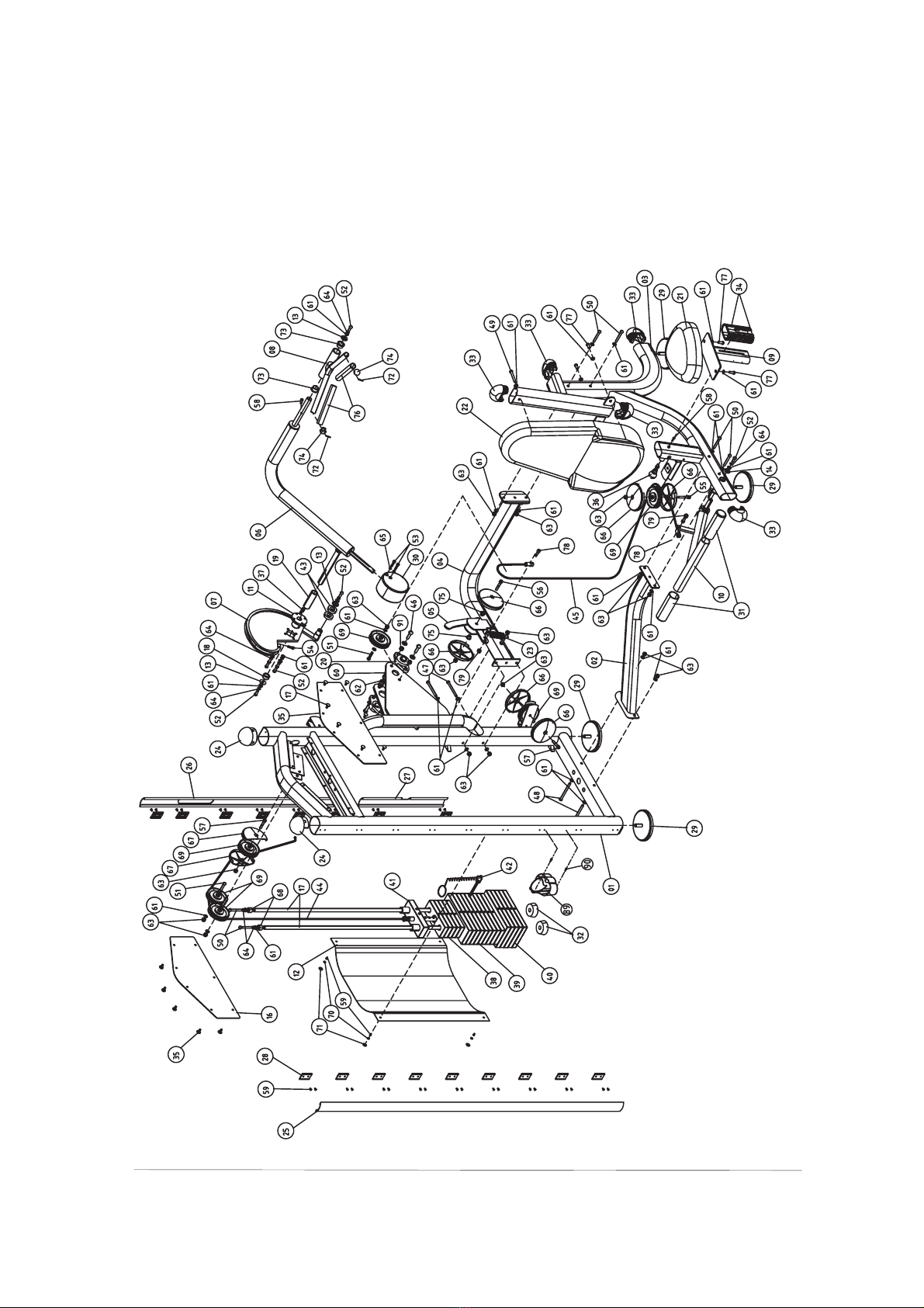
Exploded View Diagram------------------------------------------ 2
Hardware List-------------------------------------------------- 3
Parts List----------------------------------------------------- 4
Assembly instructions------------------------------------------ 5
------
----------
--

Important Safety Instructions
Before beginning any fitness program, you should obtain a complete
physical examination from your physician. When using exercise equip-
ment, basic precautions should always be taken, including the following:
* Read all instructions before using the .
arewrittentoensureyoursafetyandtoprotect
* Do not allow children on or near the equipment.
* Use the equipment only for its intended purpose as described in this
guide. Do not use accessory attachments that are not recommended
by the manufacturer: such attachments might cause injuries.
* Wear proper exercise clothing and shoes for your workout---no loose
clothing.
* Be careful when getting on or off the equipment.
* Do not overexert yourself or work to exhaustion.
* If you feel any pain or abnormal symptoms, stop your workout imme-
diately and consult your physician.
* Never operate the unit when it has been dropped or damaged.
* Never drop or insert anything into any opening in the equipment.
* Always check the unit and its cables before each use. Make sure that
all fasteners and cables are secure and in good working condition.
* Frayed or worn cables can be dangerous and may cause injury.
Periodically check these cables for any indication of wear.
* Keep hands, limbs, loose clothing and long hair well out of the way of
moving parts.
* Do not attempt to lift more weight than you can control safely.
* Do not use the equipment outdoors.
* Read each step in the assembly instructions and follow the steps in
sequence. Do not skip ahead. If you skip ahead, you may learn later
that you have to disassemble compontents and that you may have
damaged the equipment.
* Assemble and operate the equipment on a solid, level surface. Locate
the unit a few feet from walls or furniture to provide easy access.
The Super Pullover is designed for your enjoyment. By
precautions and using common sense, you will have
pleasurable hours of healthfull exercise with the
Super Pullover These instruc-
tions the unit.
following these
many safe and
equipment.
Personal Safety During Assembly
1

2
I Super Pullover
Exploded View Diagram
T8017

3
Hardware List
0 100
10 20 30 40 50 60 70 80 90 110 120 130 140 150
Inches
0123456
/
12
/
14 /
34 /
34 /
34 /
34 /
34 /
34
/
14 /
14 /
14 /
14 /
14
/
12 /
12 /
12 /
12 /
12
Millimeters

4
Parts List
Item No. Description QTY Item No. Description QTY
Allen Bolt M12×40
Allen Bolt M10×100
Screw
Decal Warning
Decal
Allen Bolt M10×115
Allen Bolt M10×75
Allen Bolt M10×70
Allen Bolt M10×45
Allen Bolt M10×25
Shoulder Bolt M8×30
M4×20
Shoulder Bolt M10×60
Shoulder Bolt M10×55
Shoulder Bolt M10×50
Screw M8×20
Screw M5×10
Washer 13× 24×1.5
Washer 11× 20×1.5
Nylon Locknut M12
Nylon Locknut M10
Spring Washer 10
Spring Washer 8
Pulley Cover
Half-pulley Cover
Rubber Cap
4.5" Pulley
Plastic Washer
Bolt Cover
Split Pin
Bronze Bushing ID25.4
Aluminium Plug
Bronze Bushing ID12
Grip
Allen Bolt M10×20
Shoulder Bolt M10×35
Nylon Locknut M8
Decal Weight Numbers
Maintenance
Decal Pinch Points
Decal Tightening
Allen Wrench S=6
Allen Wrench S=3
Decal Note
Allen Wrench S=8
Plastic Cap
Screw M6×15
Spacer
ΦΦ
ΦΦ
Φ
Φ
1
2
3
4
5
6
7
8
9
10
11
12
13
14
15
16
17
18
19
20
21
22
23
24
25
26
27
28
29
30
31
32
33
34
35
36
37
38
39
40
41
42
43
44
45
1
1
1
1
1
1
1
1
1
1
1
1
3
1
1
1
2
1
1
2
1
1
1
2
1
1
1
17
4
1
2
2
5
1
14
1
1
5
9
5
1
1
2
1
1
46
47
48
49
50
51
52
53
54
55
56
57
58
59
60
61
62
63
64
65
66
67
68
69
70
71
72
73
74
75
76
77
78
79
80
81
82
83
84
85
86
87
88
89
90
91
4
2
2
1
6
3
10
2
2
1
1
2
2
38
8
37
4
16
10
2
6
2
2
6
4
4
2
2
2
2
2
4
2
2
1
1
1
1
1
1
1
1
1
1
2
4
Main Upright
Low Cross
Seat Support
Upper Cross
"L" Cam
Arm
Cam
Handle
Seat Pad Support
StartUp Foot Frame
Flange
Weight Shroud
Washer 34×5
Washer 30×5
Rear Decal Plate
Front Decal Plate
Guide Rod
Short Spacer
Spacer
Pillow Block
Seat Pad
Back Pad
Spring
"D" End Cap
Front Side Cover
Rear Side Cover
Rear Low Cover
Plastic Block
Adj. Foot Plate
Counter Poise Block
Rubber Sleeve
Weight Rubber Bumper
RT50×100 Plug
Slide Sleeve
Button
Pop Pin
Key
5lbs Weight
10lbsWeight
15lbs Weight
Top Plate
Weight Pin
Bearing ID 25
Cable
Assistant Cable
Φ
Φ

5
Assembly instructions
Assembly of the takes professional installers
about 2 hours. If this is the first time you have assembled this
type of equipment, plan to spend more time. It is strongly recom
mended to assemble the equipment by professional installers.
You may find it quicker, safer, easier to assemble this equipment
with the help of a friend, as some of components may be large,
heavy or awkward to handle alone. It is important that you asse-
mble your product in a clean, clear, uncluttered area. This will
enable you to move around the product while you are fitting com-
onents and reduce the possibility of injury during assembly.
As with any assembled part, proper alignment and adjustment
is critical. While tightening the fasteners, be sure to leave room
for adjustments. Do not fully tighten the fasteners until instructed
to do so. Be careful to assemble the components in the sequence
presented in this guide.
Super Pullover
p
Note

6
Step1 Install the Adj. Foot Plates
Align the Adj. Foot Plates(#29) to the Main Upright(#1)
and the Seat Support(#3), then secure them by hands.
1

2
3
2
7
Step2 Assemble The Frame
1)Attach the Low Cross(#2) and the Upper Cross(#4)to
the Main Upright(#1) using:
2)Attach the Seat Support(#3) to the Upper Cross(#4)
and the Low Cross(#2) using:
two Allen Bolts(#47) M10×100
two Allen Bolts(#48) M10×115
four Nylon Locknuts(#63) M10
eight Washers(#61) 1.5
four Allen Bolt(#50) M10×70
eight Washers(#61) 1.5
four Nylon Locknuts(#63) M10
ΦΦ
ΦΦ
11× 20×
11× 20×

8
Step3 Assemble The Swivel Frame
1)Align the "L"Cam(#5) to the Upper Cross(#4) and sec-
ure it using:
2)Attach the Spring(#23) to the Upper Cross(#4) with
the Nylon Locknut (#63), next hook the "L" Cam(#5)
with it.
one Shoulder Bolt(#56) M10×55
two Pulley Covers(#66)
two Bronze Bushings ID 12(#75)
one Nylon Locknut(#63) M10
Table of contents
Popular Elliptical Trainer manuals by other brands

Bonn Germany
Bonn Germany Concept 2.2 user manual

Precor
Precor Resolute RSL 620 Assembly guide

NordicTrack
NordicTrack E 9.2 Elliptical HASZNALATI UTASITAS

Vision Fitness
Vision Fitness X6600iNetTV Assembly guide

Matrix
Matrix MX-A5x owner's manual

SportsArt Fitness
SportsArt Fitness ECO-NATURAL Elite E874 owner's manual