Icom IC-F51V User manual
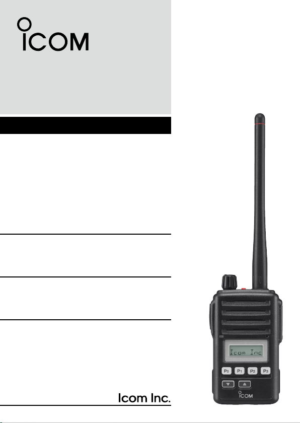
INSTRUCTION MANUAL
UHF TRANSCEIVER
iF61V
VHF TRANSCEIVER
iF51V

i
IMPORTANT
READ ALL INSTRUCTIONS carefully and completely before
using the transceiver.
SAVE THIS INSTRUCTION MANUAL— This instruction
manual contains important operating instructions for the IC-F51V
v h f t r a n s c e i v e r and IC-F61V u h f t r a n s c e i v e r .
EXPLICIT DEFINITIONS
WORD DEFINITION
RDANGER! Personal death, serious injury or an explosion
may occur.
RWARNING! Personal injury, fire hazard or electric shock
may occur.
CAUTION Equipment damage may occur.
NOTE If disregarded, inconvenience only. No risk of
personal injury, fire or electric shock.
OPERATING NOTES
• When transmitting with a portable radio, hold the radio in a vertical
position with its microphone 5 to 10 cm away from your mouth. Keep
the antenna at least 2.5 cm from your head and body.
• If you wear a portable two-way radio on your body, ensure that the
antenna is at least 2.5 cm from your body when transmitting.
Icom, Icom Inc. and the Icom logo are registered trademarks of Icom Incor-
porated (Japan) in Japan, the United States, the United Kingdom, Germany,
France, Spain, Russia and/or other countries.

PRECAUTIONS
RDANGER! NEVER short the terminals of the battery pack.
RDANGER! Use and charge only specied Icom battery packs with
Icom radios or Icom chargers. Only Icom battery packs are tested and
approved for use with Icom radios or charged with Icom chargers. Using
third-party or counterfeit battery packs or chargers may cause smoke,
fire, or cause the battery to burst.
RWARNING! NEVER hold the transceiver so that the antenna is
very close to, or touching exposed parts of the body, especially the face
or eyes, while transmitting. The transceiver will perform best if the micro-
phone is 5 to 10 cm away from the lips and the transceiver is vertical.
RWARNING! NEVER operate the transceiver with a headset or
other audio accessories at high volume levels.
CAUTION:
NEVER connect the transceiver to a power source other
than the BP-226 or BP-227. Such a connection will ruin the transceiver.
CAUTION:
MAKE SURE the flexible antenna and battery pack are
securely attached to the transceiver, and that the antenna and battery
pack are dry before attachment. Exposing the inside of the transceiver to
water will result in serious damage to the transceiver.
DO NOT push the PTT when not actually desiring to transmit.
DO NOT use or place the transceiver in direct sunlight or in areas with
temperatures below –25°C or above +55°C; except for China. (Below
–30°C or above +60°C for China.)
DO NOT modify the transceiver for any reason.
DO NOT operate the transceiver near unshielded electrical blasting
caps or in an explosive atmosphere. The IC-F51V/F61V series transceiv-
ers are not the explosion-proof construction.
BE CAREFUL!
The transceiver meets IPX7* requirements for water-
proof protection. However, once the transceiver has been dropped, wa-
terproof protection cannot be guaranteed because of possible damage to
the transceiver's case or the waterproof seal.
* Only when the supplied battery pack, exible antenna and jack cover
are attached.
ii

TABLE OF CONTENTS
iii
IMPORTANT.................................................................................................... i
EXPLICIT DEFINITIONS................................................................................. i
OPERATING NOTES.......................................................................................i
PRECAUTIONS.............................................................................................. ii
TABLE OF CONTENTS................................................................................. iii
1 ACCESSORIES....................................................................................1–3
■ Supplied accessories ............................................................................1
■ Accessory attachments .........................................................................2
2 PANEL DESCRIPTION.......................................................................4–13
■ Front, top and side panels.....................................................................4
■ Function display ....................................................................................6
■ Programmable function keys.................................................................8
3 BASIC OPERATION.........................................................................14–23
■ Turning power ON ...............................................................................14
■ Channel selection................................................................................14
■ Call procedure.....................................................................................15
■ Receiving and transmitting..................................................................16
■ User set mode.....................................................................................20
■Emergency transmission.....................................................................21
■ Scrambler function ..............................................................................21
■Stun function .......................................................................................21
■ Recording function (Depends on the version).....................................22
4 BATTERY CHARGING .....................................................................24–31
■ Caution................................................................................................24
■ Optional battery chargers....................................................................27
5 BATTERY CASE...............................................................................32–33
■ Optional battery case (BP-226)...........................................................32
6 SPEAKER-MICROPHONE...............................................................34–35
■ Optional HM-168 description...............................................................34
■ Attachment ..........................................................................................35
7 SWIVEL BELT CLIP .........................................................................36–37
■ MB-86 contents ...................................................................................36
■ Attaching .............................................................................................36
■ Detaching ............................................................................................37
8 OPTIONS..........................................................................................38–41
9 COUNTRY CODE LIST ..........................................................................42

1
1
ACCESSORIES
1
2
3
4
5
6
7
8
9
10
11
12
13
14
15
16
17
18
19
20
■Supplied accessories
*There are no names on the programmable function keys since
the functions can be freely assigned to [P0] to [P3], [Red], [ ]
and [ ] keys.
Attach the supplied key stickers above the appropriate keys for
easy recognition of that key’s assigned function.
Battery packAntenna
Belt clip
Key sticker*Jack cover
2
1ACCESSORIES
■Accessory attachments
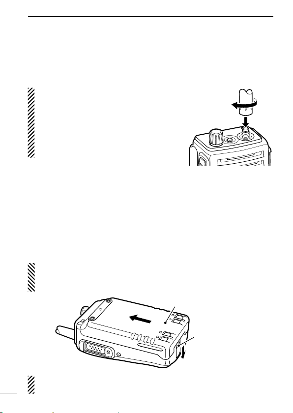
DFlexible antenna
Connect the supplied flexible antenna to the antenna connector.
CAUTION:
• NEVER carry the transceiver by
holding the antenna.
• DO NOT connect the antenna other
than listed on page 39.
• Transmitting without an antenna may
damage the transceiver.
DBattery pack
To attach the battery pack:
Slide the battery pack on the back of the transceiver in the direction
of the arrow (q), then lock it with the battery release button.
• Slide the battery pack until the battery release button makes a ‘click’
sound.
To release the battery pack:
Push the battery release button in the direction of the arrow (w) as
shown below. The battery pack is then released.
NEVER release or attach the battery pack when the transceiver is wet
or soiled. This may result water or dust getting into the transceiver/bat-
tery pack and may result in the transceiver being damaged.
q
w
Battery pack
Battery release
button
NOTE: Keep the battery pack terminals clean. It’s a good idea to
clean the battery pack terminals once a week.
3
1
ACCESSORIES
1
2
3
4
5
6
7
8
9
10
11
12
13
14
15
16
17
18
19
20
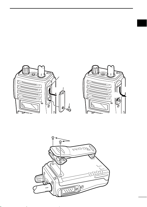
DJack cover
Attach the jack cover when the optional equipment is not used.
DBelt clip
Attach the belt clip to the back of the transceiver with the supplied
screws.
Supplied screws
w
Jack cover
[SP MIC] jack
Screw
q
e
r
To attach the jack cover:
qInsert the jack cover into the
[SP MIC] jack.
w Tighten the screw.
To detach the jack cover:
e Unscrew the screw using a
phillips screwdriver.
rDetach the jack cover for the
optional equipment connec-
tion.
4
2PANEL DESCRIPTION
■Front, top and side panels
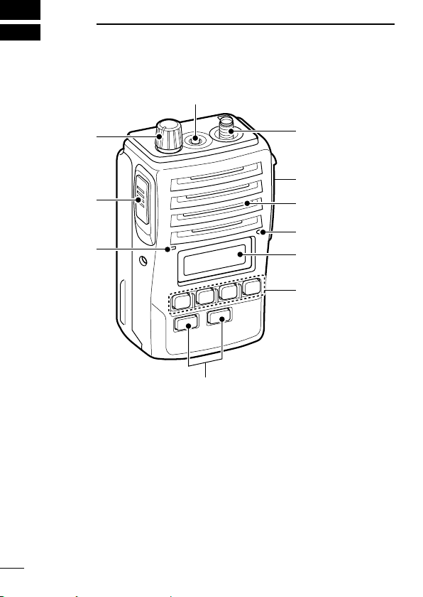
qVOLUME CONTROL [VOL]
Turns power ON and adjusts the audio level.
wRED BUTTON
The desired function can be assigned by your dealer. (p. 8)
eANTENNA CONNECTOR
Connects the supplied antenna. (p. 2)
Microphone
Function display
(p. 6)
w
e
r
t
y
u
q
iSpeaker

5
2
PANEL DESCRIPTION
2
rEXTERNAL SPEAKER-MICROPHONE JACK [SP MIC]
Connects the optional speaker-microphone, etc.
tDEALER-PROGRAMMABLE KEYS [P0] to [P3]
The desired functions can be assigned independently by your
dealer. (p. 8)
yCH UP AND DOWN KEYS [ ]/[ ]
Push to select an operating channel, etc.
*Desired functions can be assigned independently by your dealer.
(p. 8)
uTRANSMIT/BUSY INDICATOR
Lights red while transmitting; lights green while receiving a sig-
nal, or when the squelch is open.
iPTT SWITCH [PTT]
➥ Push and hold to transmit; release to receive.
➥ When the recording function is activated, TX voice message
can be recorded while pushing and holding [PTT]. (p. 22)
[SP MIC] jack cover
NOTE: KEEP the [SP MIC]
jack cover attached to the
transceiver when the optional
equipment is not used.
(See p. 3 for details)
6
2PANEL DESCRIPTION
■Function display
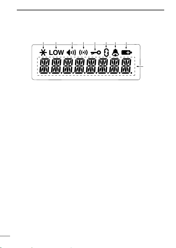
q RECORD INDICATOR
➥ Appears when an unread message is in the memory.
➥ Blinks while recording.
w LOW POWER INDICATOR
Appears when low output power is selected.
eAUDIBLE INDICATOR
➥
Appears when the channel is in the ‘audible’ (unmute) condition.
➥ Appears when the specied 5-tone/BIIS*1/MDC*2code is re-
ceived.
rCOMPANDER INDICATOR
Appears when the compander function is activated.
tKEY LOCK INDICATOR
Appears when the key lock function is activated.
ySCRAMBLER INDICATOR
Appears when the voice scrambler function is activated.
uBELL INDICATOR
Appears/blinks when the specific 5-tone/BIIS*1/MDC*2code is
received, according to the pre-programming.
qtiuyrew
o
Other manuals for IC-F51V
1
This manual suits for next models
1
Table of contents
Other Icom Transceiver manuals