i-PRO WV-QEM506 User manual
1
• Before attempting to connect or install this product, please read these instructions carefully
and save this manual for future use.
• The external appearance and other parts shown in this manual may differ from the actual
product within the scope that will not interfere with normal use due to improvement of the
product.
i-PRO Co., Ltd. assumes no responsibility for injuries or property damage resulting
from failures arising out of improper installation or operation inconsistent with this
documentation.
“<Control No.: C****>” used in these documents should be used to search for
information on our technical information website (https://i-pro.com/global/en/
surveillance/training-support/support/technical-information) and will guide you
to the right information.
https://www.i-pro.com/
© i-PRO Co., Ltd. 2023
C0123-0
PGQP3662ZA
Installation Guide
Included Installation Instructions
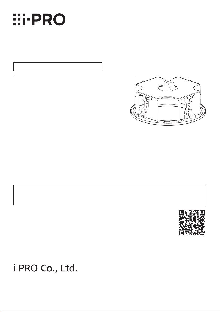
Ceiling Mount Bracket
Model No. WV-QEM506

2
Caution:
• Before attempting to connect or operate
this product, please read these instruc-
tions carefully.
Notice:
• This product is not suitable for use in loca-
tions where children are likely to be pres-
ent.
• Do not install this product in locations
where ordinary persons can easily reach.
• For information about screws and other
parts required for installation, refer to the
corresponding section of this document.
Precautions
Do not use this bracket except with suitable cameras.
Failure to observe this may cause a drop resulting in injury or accidents.
Refer installation work to the dealer.
Installation work requires technique and experience. Failure to observe this may cause fire,
electric shock, injury, or damage to the product.
Be sure to consult the dealer.
Take measures of protection against this product falling.
Failure to observe this may cause a drop resulting in injury or accidents. Be sure to install
the safety wire.
The screws and bolts must be tightened to the specied torque.
Failure to observe this may cause a drop resulting in injury or accidents.
Install the product accurately and securely on a ceiling in accordance with the
installation instructions.
Failure to observe this may cause injury or accidents.
Do not rub the edges of metal parts with your hand.
Failure to observe this may cause injury.
When using this product, also read the “Precautions” described in the operating
instructions for the camera to be attached.
Preface
This product is a ceiling embedded bracket that is designed to mount the network camera on a
ceiling. This bracket can be used for an area with weak pull-out strength such as plasterboard in
a double ceiling, and the embedded type makes the visible part of the camera smaller.
The latest information about the supported cameras <Control No.:C0501>.

3
Specifications
Ambient operating
temperature:
–50 °C to +60 °C {–58 °F to +140 °F}
Dimensions: ø328 mm × 153 mm (H)* {ø12-29/32 inches × 6-1/32 inches}
*Including decorative cover thickness: 17.5 mm {11/16 inches}
Mass: Approx. 2.0 kg{4.42 lbs}
Finish: Main body: Surface treatment steel sheet
Decorative cover:
ABS resin i-PRO white <WV-QEM506-W>
Black <WV-QEM506-B>
Precautions for installation
In order to prevent injury, the product must be securely mounted to the ceiling
according to the Installation Guide.
This product is designed to be used indoors.
This product is not operable outdoors. Do not expose this product to direct sunlight for hours
and do not install the product near a heater or an air conditioner. Otherwise, it may cause
deformation, discoloration and malfunction. Keep this product away from water and moisture.
Installation area for this product
Make sure that the installation area is strong enough to hold
the total weight of the camera assembly before installation.
The installation area shall have 165 mm {6-1/2 inches} or
more space behind the ceiling.
The thickness of the ceiling board for installation can range
between 9mm {11/32inches} and 40mm {1-9/16inches}.
Make sure to remove this product if it will no
longer be used.
165mm
{6-1/2inches}
or more
Ceiling board: between
9mm {11/32inches} and
40mm {1-9/16inches}
Standard Accessories
Safety wire* .......................................... 1 pc.
Safety wire angle*................................. 1 pc.
Fixing screw for attachment plate (M4 × 8 mm
{5/16 inches}) ........5 pcs. (of them, 1 for spare)
Template............................................... 1 pc.
Decorative cover................................... 1 pc.
* The product is shipped in a state where the safety wire is attached to the safety wire angle.
Other items that are needed (not included)
Anchor bolt (M10)*.............................. 2 pcs. Nut (M10) .......................................... 6 pcs.
* One anchor is used for securing the mounting chassis, and the other anchor is used for
connecting the safety wire. (See Step2)
IMPORTANT
• Prepare anchor bolts according to the material and strength of the area where the prod-
uct is to be installed. The pull-out strength of the anchor bolt shall be more than 5 times
of the total weight of the installed devices (including the camera body, ceiling mount
bracket, anchor bolts, and all other parts).

4
Installation
Refer to the operating instructions of the camera for details on the camera
installation (including the camera mounting, cable connection and adjustment).
Step 1
Create a ø300 mm {11-13/16 inches} hole.
Visual reference for
the decorative cover
Ceiling surface
ø300 mm
{11-13/16 inches}
Brand logo side
Step 2 Install two anchor bolts (M10: locally procured) into the ceiling.
①Determine the anchor bolt length (for securing the mounting chassis) by use of Template
(accessory).
②Position the nut (locally procured) by use of Template and mount the nut.
(The distance between the bottom surfaces of the ceiling board and nut shall be 136mm
{5-11/32 inches}.)
Anchor bolt
(for connecting the safety wire)
②Mount a nut
①Determine the anchor bolt length
Install the anchor bolt in the center of the hole
136mm {5-11/32 inches}
Template
Ceiling board
Anchor bolt
(for securing the mounting chassis)
1 m {3.28 feet} or less
IMPORTANT:
• When the existing anchor bolt is used as an anchor bolt for connecting the safety wire,
make sure that the distance between the anchor bolt and camera mounting position is
1m {3.28feet} or less.

5
Step 3 Secure the safety wire angle (accessory) to the anchor bolt (for
connecting the safety wire), and connect the safety wire
(accessory).
①Mount a nut so that the safety wire
angle is secured on the anchor bolt.
②Remove the safety wire from the safety
wire angle.
③Insert the groove of the portion ❶of
the safety wire angle into the anchor
bolt.
④Close the safety wire angle while
inserting the groove of the portion ❷of
the safety wire angle into the anchor
bolt.
⑤Connect the safety wire to the safety
wire angle again.
⑥Engage the nut from beneath, and
secure the safety wire angle with top
and bottom nuts.
⑦Engage another nut from beneath to
tighten and secure the nut that was
engaged from beneath in ⑥in a
double nut fashion.
<Image of safety wire connection>
Existing anchor bolt
Safety wire
Safety wire angle
Nut
(locally procured)
⑥⑦
①
Upper side
Lower side
Safety wire
③Insert
②Remove
④Close
❷
❶
⑤Connect
Safety wire angle
Anchor bolt
Note:
• When the existing anchor bolt
that has been installed is used
for connecting the safety wire,
the use of 2 spacer nuts is
helpful.
Spacer nuts
Spacer nuts
Safety wire angle
Existing anchor bolt
Safety wire

6
Step 4 Attach the safety wire.
Attach the safety wire to the mounting
chassis as shown in the illustration below.
Safety wire
(Accessory)
Ceiling board
Cables
Mounting
chassis
Fix the hook of the safety wire to this
product.
Roof space
Installation onward for the descriptions of the cable and the safety wire may be omitted.
Step 5 Check the orientation for inserting the mounting chassis into
the ceiling.
To align the i-PRO logo on the decorative cover, align the direction of the mounting chassis
before inserting the mounting chassis into the mounting hole on the ceiling board.
Mounting hole
Direction of
brand logo
Direction of
brand logo

7
Step 6 Secure the mounting chassis.
②
①
③
Recommended
tightening torque:
0.78 N·m {0.58 lbf·ft}
Ceiling board fixing bracket
(4 places)
Ceiling board
fixing screw
(4 places)
Double nuts
(locally procured)
Ceiling board
Ceiling board
fixing bracket
Ceiling board
fixing screw
Anchor bolt
(for securing the
mounting chassis)
When inserting the mounting
chassis

8
Step 7 Pull out the camera mounting stage
①Loosen the screws.
①①
②②
③
③
④
④

9
Step 8 Install the attachment plate
Camera mounting method
Fixing screw for
attachment plate (accessory)
Attachment plate
(camera accessory)
ARecommended tightening torque:
0.78 N·m {0.58 lbf·ft}
For Step 9, follow the installation procedure in the camera
installation section or the installation procedure leaflet.
Step 9
Bit (camera accessory)
Recommended tightening torque:
1.2 N·m {0.89 lbf·ft}

10
Step 10 Mount the decorative cover.
②
②
①
①
③
③
Recommended tightening torque:
0.4 N·m {0.3 lbf·ft}
I Mark
(4 places)
Decorative cover
fixing screw
Decorative cover
protrusions
(4 places)
Hook
(4 places)
②
②
①
③
①
• Recommended tightening torque:
0.78 N·m {0.58 lbf·ft}
• There are two places where the decorative
cover fixing screw can be fixed: the position
shown in the illustration and the opposite side.
Table of contents
Other i-PRO TV Mount manuals


