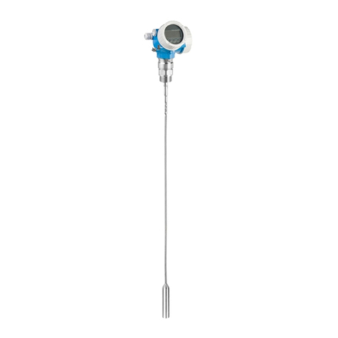
HYDROLOGICAL SERVICES HYC 230 User manual

Hydra-Pulse HYC Level Radar Manual
HYC 230 Radar Sensor for continuous level measurement
SDI-12 Version

2
Product description
Hydra-Pulse HYC 230 • SDI-12
Product description
Configuration
The scope of delivery encompasses:
•Radar sensor
•Counter nut G1 1)
•Information sheet " Documents and software" with:
– Instrument serial number
– QR code with link for direct scanning
•Information sheet " PINs and Codes" (with Bluetooth versions)
with:
– Bluetooth access code
•Information sheet " Access protection" (with Bluetooth versions)
with:
– Bluetooth access code
– Emergency Bluetooth unlock code
– Emergency device code
The further scope of delivery encompasses:
•Documentation
– Ex-specic"Safety instructions" (with Ex versions)
– Radio licenses
– Ifnecessary,furthercerticates
Note:
Optional instrument features are also described in this operating
instructions manual.The respective scope of delivery results from the
orderspecication.
This operating instructions manual applies to the following instrument
versions:
•Hardware version from 1.0.0
•Software version from 1.2.0
Scope of delivery
Scope of this operating
instructions
1) With G thread

3
Hydra-Pulse HYC 230 • SDI-12
Principle of operation
Hydra-Pulse HYC 230 is a radar sensor for non-contact, continuous
level measurement. It is suitable for liquids and solids in practically all
industries.
The device is designed for connection to data loggers with SDI-12
interface, making it particularly suitable for battery-powered applica-
tions requiring low power consumption.
The Hydra-Pulse HYC 230 can be operated at any data logger with
SDI-12 interface. The sensors are powered via the +12 V line of the
three-wire connection cable.
The instrument emits a continuous, frequency-modulated radar signal
throughitsantenna.Theemittedsignalisreflectedbythemedium
andreceivedbytheantennaasanechowithmodifiedfrequency.The
frequency change is proportional to the distance and is converted
into the level.
Adjustment
The optionally integrated Bluetooth module enables a wireless
adjust-ment of Hydra-Pulse HYC 230 via standard adjustment
devices:
•Smartphone/tablet (iOS or Android operating system)
•PC/notebook with Bluetooth USB adapter (Windows operating
system)
13
2
The SDI-12 data communication is controlled by commands from
the SDI-12 data logger via the signal cable.
Application area
Power supply and signal
processing
Functional principle
Wireless adjustment
Adjustment via the signal
cable
Download our easy to use App for your phone or tablet.
Search for "Wireless Device Configurator" at the App Store
or on Google Play.
Fig. 3: Wireless connection to standard operating devices with integrated
Bluetooth LE
1 Sensor
2 Smartphone/Tablet
3 PC/Notebook

4
Product description
Hydra-Pulse HYC 230 • SDI-12
12
Fig. 4: Connection of Hydra-Pulse HYC 230 SDI-12 to the data logge
1 Sensor
2 Data logger
Packaging, transport and storage
Your instrument was protected by packaging during transport. Its
capacity to handle normal loads during transport is assured by a test
based on ISO 4180.
The packaging consists of environment-friendly, recyclable card-
board. For special versions, PE foam or PE foil is also used. Dispose
of the packaging material via specialised recycling companies.
Transport must be carried out in due consideration of the notes on the
transport packaging. Nonobservance of these instructions can cause
damage to the device.
The delivery must be checked for completeness and possible transit
damage immediately at receipt. Ascertained transit damage or con-
cealed defects must be appropriately dealt with.
Up to the time of installation, the packages must be left closed and
stored according to the orientation and storage markings on the
outside.
Unless otherwise indicated, the packages must be stored only under
the following conditions:
•Not in the open
•Dry and dust free
•Not exposed to corrosive media
•Protected against solar radiation
•Avoiding mechanical shock and vibration
•Storage and transport temperature see chapter " Supplement -
Technical data - Ambient conditions"
•Relative humidity 20 … 85 %
Accessories
Screwedangesareavailableindierentversionsaccordingtothe
following standards: DIN 2501, EN 1092-1, BS 10, A SME B 16.5,
JIS B 2210-1984, GOST 12821-80.
Packaging
Transport
Transport inspection
Storage
Storage and transport
temperature
Flanges

5
Product description
Hydra-Pulse HYC 230 • SDI-12
Welded sockets are used to connect the devices to the process.
Threaded adapters enable simple adaptation of devices with stand-
ardthreadedttings,e.g.toprocess-sidehygieneconnections.
The mounting accessories are used for stable mounting of the device
at the measuring point. The parts are available in various versions and
sizes.
Welded sockets and
adapters
Mounting strap

6
Mounting
Hydra-Pulse HYC 230 • SDI-12
Mounting
General instructions
The instrument is suitable for standard and extended ambient condi-
tions acc. to DIN/EN/IEC/ANSI/ISA/UL/CSA 61010-1. It can be used
indoors as well as outdoors.
Note:
For safety reasons, the instrument must only be operated within the
permissibleprocessconditions.Youcannddetailedinformationon
the process conditions in chapter " Technical data" of the operating
instructions or on the type label.
Hence make sure before mounting that all parts of the instrument ex-
posed to the process are suitable for the existing process conditions.
These are mainly:
•Active measuring component
•Processtting
•Process seal
Process conditions in particular are:
•Process pressure
•Process temperature
•Chemical properties of the medium
•Abrasionandmechanicalinuences
Mounting versions
For the wall mounting, a mounting bracket with opening for thread G1
is recommended.The mounting of the device in the bracket is carried
out via the supplied G1 counter nut of plastic. Take note of chapter "
Mounting instructions" for the recommended distance to the wall.
> 200 mm
(7.87
")
Fig. 5: Mounting via a mounting bracket
Ambient conditions
Process conditions
Mounting bracket

7
Mounting
Hydra-Pulse HYC 230 • SDI-12
Mounting instructions
Radar sensors for level measurement emit electromagnetic waves.
The polarization is the direction of the electrical component of these
waves.
The position of the polarisation is in the middle of the type label on the
instrument.
1
Fig. 6: Position of the polarisation
1 Middle of the type label
Note:
When the device is rotated, the direction of polarization changes and
hencetheinuenceofthefalseechoonthemeasuredvalue.Please
keep this in mind when mounting or making changes later.
Mount the device at a position that is at least 200 mm (7.874 in) away
from a wall or structural parts (see illustrations above).
If you cannot maintain this distance, you should carry out a false
signal suppression during setup.This applies particularly if buildup
on the wall or structural parts is to be expected. In such cases, we
recommend repeating the false signal suppression at a later date with
existing buildup.
The centre of the antenna lens is the beginning of the measuring
range and at the same time the reference plane for the min./max.
adjustment, see following diagram:
1
Fig. 7: Reference plane
1 Reference plane
Donotmounttheinstrumentsinorabovethellingstream.Makesure
thatyoudetectthemediumsurface,nottheinowingproduct.
Polarisation
Installation position
Reference plane
Inowingmedium

8
Mounting
Hydra-Pulse HYC 230 • SDI-12
Measurement setups - Gauge
In general, the following must be observed while mounting the sensor:
•Mounting on solid bracket or mounting bracket
•High or low water for mounting position
•Measurementonwatersurfaceasataspossibleincalmarea
•Minimum distance to the max. water level
The following examples serve as an overview for gauge measure-
ment.
Fig. 14: Gauge measurement river, sensor mounting on bridge pier
River level
Fig. 15: Gauge measurement dam, sensor mounting on bracket
Dam gauge

9
Mounting
Hydra-Pulse HYC 230 • SDI-12
Fig. 16: Gauge measurement deep well, sensor mounting on lid
Deep well level

10
Connecting to power supply
Hydra-Pulse HYC 230 • SDI-12
Connecting to power supply
Preparing the connection
Always keep in mind the following safety instructions:
•Carryoutelectricalconnectionbytrained,qualiedpersonnel
authorised by the plant operator
Warning:
Only connect or disconnect in de-energized state.
The device is supplied with power via an SDI-12 datalogger.
Note:
Power the instrument via an energy-limited circuit (power max. 100 W)
acc. to IEC 61010-1, e.g.
•Class 2 power supply unit (acc. to UL1310)
•SELV power supply unit (safety extra-low voltage) with suitable
internal or external limitation of the output current
Thedataforpowersupplyarespeciedinchapter"Technical data".
Thedeviceissuppliedwithaxedconnectedcable.Ifanextensionis
required, a standard three-wire cable can be used.
If electromagnetic interference is expected which is above the test
values of EN 61326-1 for industrial areas, shielded cable should be
used.
We recommend to connect the cable screening to ground potential at
one end on the supply side when using shielded cable.
Wiring plan
1
2
3
4
Fig. 19: Wire assignment in permanently connected connection cable
Wire colour Function Polarity
1 Brown Voltage supply Plus (+)
2 Blue Voltage supply Minus (-)
3 White SDI data Plus (+)
4 Shielding
Safety instructions
Voltage supply
Connection cable
Cable screening and
grounding
Wire assignment, con-
nection cable
Table of contents
Popular Radar manuals by other brands

SAW D2L
SAW D2L Valentine One Gen2 owner's manual

Raymarine
Raymarine Raytheon R20X instruction manual

Simrad
Simrad CA34 manual

Endress+Hauser
Endress+Hauser Micropilot FMR67B Brief operating instructions

Endress+Hauser
Endress+Hauser Levelflex M FMP45 operating instructions

ECHOMAX
ECHOMAX Active-X-Band manual