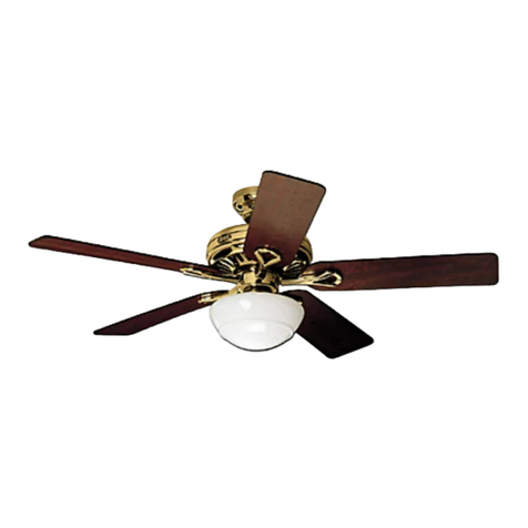
Hunter TRAK WIRED User manual
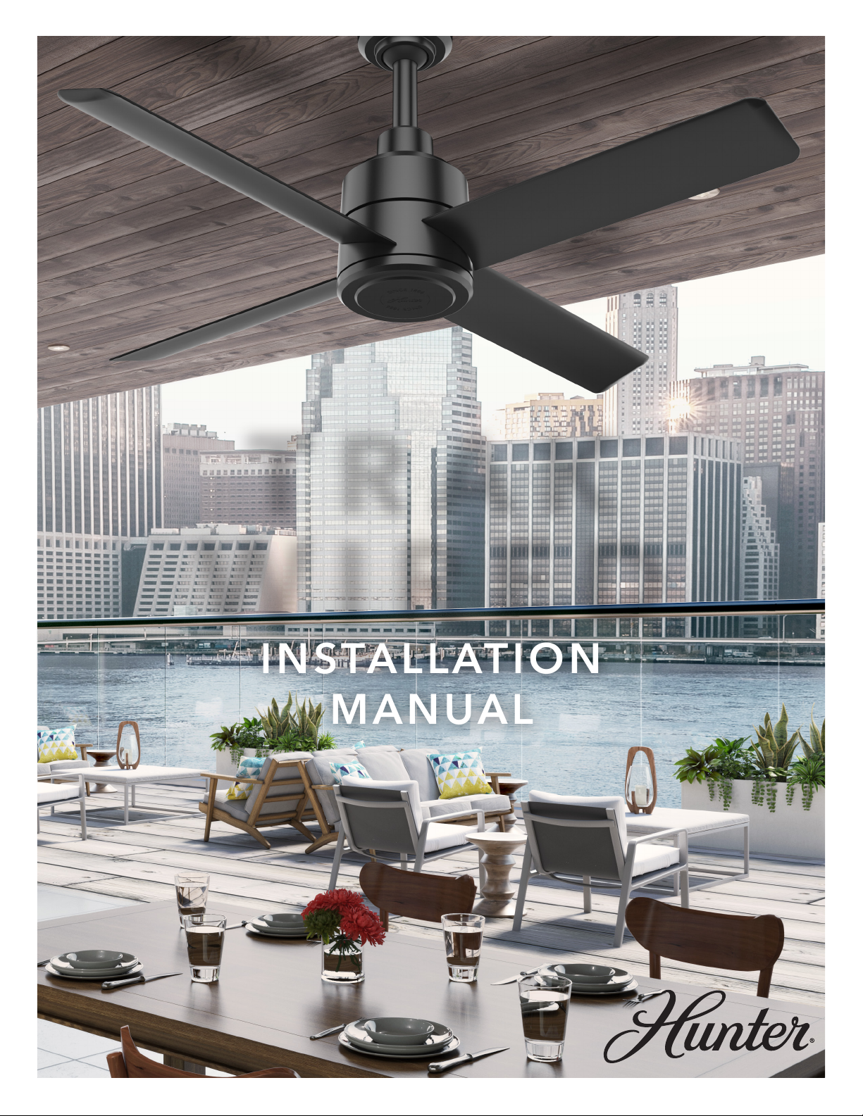
INSTALLATION
MANUAL
TRAK
WIRED

Contents
BEFORE YOU BEGIN
INSTALLATION
REFERENCE
Safety & Precautions
Fan Placement
Pre-Installation
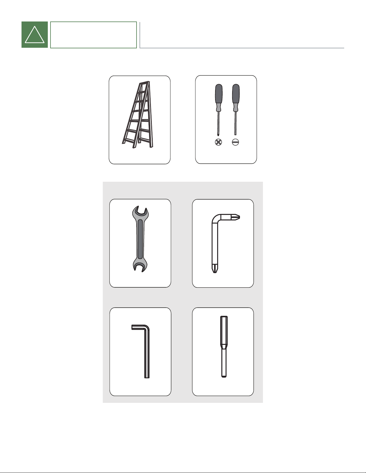
Tools Needed
InThe Box
3
6
9
10
11
12
13
14
15
16
18
19
20
21
22
23
23
24
Step 1: Ceiling Bracket
Step 2: Downrod
Step 3: MotorAssembly
Step 4: Retention System
Step 5: Wiring
Step 6: Mounting
Step 7: Blades
Step 8: Control Method
Wiring Suggestion
Maintenance
Fire Relay Wiring
BMS Gateway Connection
Troubleshooting
!
LEGACY
The Hunter legacy is not
only about quality—it’s
about longevity.We
invented the ceiling fan.
We build fans that last,
fans that are designed as
fans.We design our fans
while considering each
person in the process—
from the installer to the
owner.
AUTHENTICITY
In a world full of
impersonators,be an
original.We invented
the ceiling fan,and we
stand behind our
products.
3
BEFORE YOU BEGIN SAFETY & PRECAUTIONS
Important Safety Information
TopreventSERIOUSINJURY,DEATH,andPROPERTYDAMAGE,youshouldread,understand,andfollowthewarningsandinstructionsin
thismanualbeforeinstallingoroperatingthefan.
FIRE, ELECTRIC SHOCK AND CRUSH HAZARDS.
TO PREVENT SERIOUS INJURY OR DEATH:
• To reduce the risk of re, electrical shock, or personal injury, mount fan directly from building structure and/or an
outlet box marked acceptable for fan support of 70 lbs (31.8 kg) and use the mounting screws provided with the
outlet box.
• To avoid possible electrical shock, before installing or servicing your fan, disconnect the power by turning off the
circuit breakers to the outlet box and associated wall switch location. If you cannot lock the circuit breakers in the
off position, securely fasten a prominent warning device, such as a tag, to the service panel.
• To reduce the risk of electric shock, this fan must be installed with an isolating wall control/switch.
• To reduce the risk of personal injury, do not insert foreign objects in between rotating fan blades.
• This appliance can be used by children aged from 8 years and above and persons with reduced physical, sensory
or mental capabilities or lack of experience and knowledge if they have been given supervision or instruction
concerning use of the appliance in a safe way and understand the hazards involved. Children shall not play
with the appliance. Cleaning and user maintenance shall not be made by children without supervision. It is
recommended that children be supervised to ensure that they are not using the appliance improperly.
• To reduce the risk of re or electric shock or injury to persons, do not use replacement parts that have not been
recommended by the manufacturer (e.g. parts made at home using a 3D printer).
Installation, Adjustment, Repair or Maintenance Must Be Performed By Qualied Personnel.
Followallsafetypracticesandinstructionsduringtheinstallation,operationandservicingofthefan.Failuretoapplythesesafetypractices
couldresultindeathorseriousinjury.Ifyoudonotunderstandtheinstructions,pleasecallourTechnicalDepartmentat1-844-591-FANS
(3267),oremailusat:[email protected]forguidance.
Always Check Federal, State and Local Codes Before Installing Fan.
Code compliance is the responsibility of the installer. Check all relevant codes to make sure that all product certications, product listings
andbuildingregulationsaremet.
READ AND SAVE THESE INSTRUCTIONS.Thismanualmustalwaysbekeptwiththefanandshouldremainwiththefanifitistransferred
orsold. Alwaysgivemanualtofanownerfollowinginstallation.
5007479
!
4
BEFORE YOU BEGIN
!
TO PREVENT SERIOUS INJURY OR DEATH:
• BEFORE installing or servicing your fan, ALWAYS disconnect the power by turning off the circuit breaker or
breakers, to the fan locations and conrm Lockout/Tagout procedures are in place. If you cannot lock the circuit
breakers in the off position, securely fasten a prominent warning device, such as a tag, to the electrical panel.
• All wiring must be in accordance with national and local electrical codes, including ANSI/NFPA 70. If you are
unfamiliar with wiring or in doubt, consult a qualied electrician.
• Do not use an extension cord with fan.
• Do not remove covers while power is on.
• Do not use improper voltage source.
All fan controls and incoming power should be installed only by qualied technicians familiar with the requirements of the National
ElectricalCodeandlocalcodes.Failuretofollowtheseguidelineswillvoidthemanufacturer’swarranty.
All electrical controls are congured at the factory and are ready to use. No user adjustments are available. Follow the included installation
instructions when installing this device to ensure proper operation. Do not make any changes to any part of the fan without rst consulting
HunterIndustrial.InstallationistobeinaccordancewithANSI/NFPA70:NationalElectricalCodeandlocalcodes.
Theuseris responsible forcompliance withall internationaland NationalElectricalCoderequirements withrespectto grounding of all
equipment.Manyofthepartsof thisunitoperateatlinevoltage.
Before installing, servicing, or cleaning the unit, switch power off at the service panel, lock the service disconnecting means, and conrm
Lockout/Tagout procedures are in place to prevent power from being switched on accidentally. When the service disconnect means
cannotbelocked,securelyfastenaprominentwarningsign,suchasatag,totheservicepanel.
Toreducetheriskofelectricshock,seriousinjury,anddeath,onlyusethisunitasintendedbythemanufacturer.Ifyouhaveanyquestions,
callourTechnicalDepartmentat1-844-591-FANS(3267),oremailusat:[email protected].
5007479
SAFETY & PRECAUTIONS
ELECTRIC SHOCK HAZARD
5
BEFORE YOU BEGIN SAFETY & PRECAUTIONS
!
Weight and Torque Considerations
Alwaysmountfandirectlytobuildingstructurethatcanwithstandapproximatelydouble(2x)themaximumhangingweightofthefan.
Thehanging weightof a8’ fanwitha standard11”downrodis 50lbs.The maximumhanging weightof a8’ fanwitha 59”downrodis
55lbsandamaximumtorqueof 7ft-lbs.
HunterFanprovidesguidelinesformountingfans;however,itisthesoleresponsibilityofthebuildingownerandinstallertoensurethe
safetyof themounting systemand RetentionCable,the buildingstructureissound,and theinstallation complieswithallfederal,state
andlocalcodes.
To prevent serious injury or death, ALWAYS attach the Retention Cable to the fan motor and secure to the building structure on
EVERY fan.
The Retention Cable, if installed per Hunter Industrial specications, can limit the distance the fan could fall in the unlikely event of
mountingsystemfailure. Failuretoinstallandtosecuretheretentioncablewillvoidyourwarranty.
Always use Personal Protective Equipment
YoushouldalwayswearPersonalProtectiveEquipment,suchasaHardHat,SafetyGlasses,andaFallHarnesswheninstallingindustrial
fans.
Service
If the fan does not operate properly using the procedures in this manual, remove all power to the unit and contact our Technical
Departmentforfurtherassistanceat1-844-591-FANS(3267),oremailusat:[email protected].
Damaged Equipment
Never operate or install any fans or fan accessories that appear to be damaged.Failure to follow this instruction can result in death,
seriousinjuryorequipmentdamage.
Toreducetheriskofpersonalinjury,donotbendthebladesorbladeholderswheninstallingorcleaningthefan.
Donotinsertforeignobjectsinbetweenrotatingfanblades.
CRUSH HAZARD
6
BEFORE YOU BEGIN
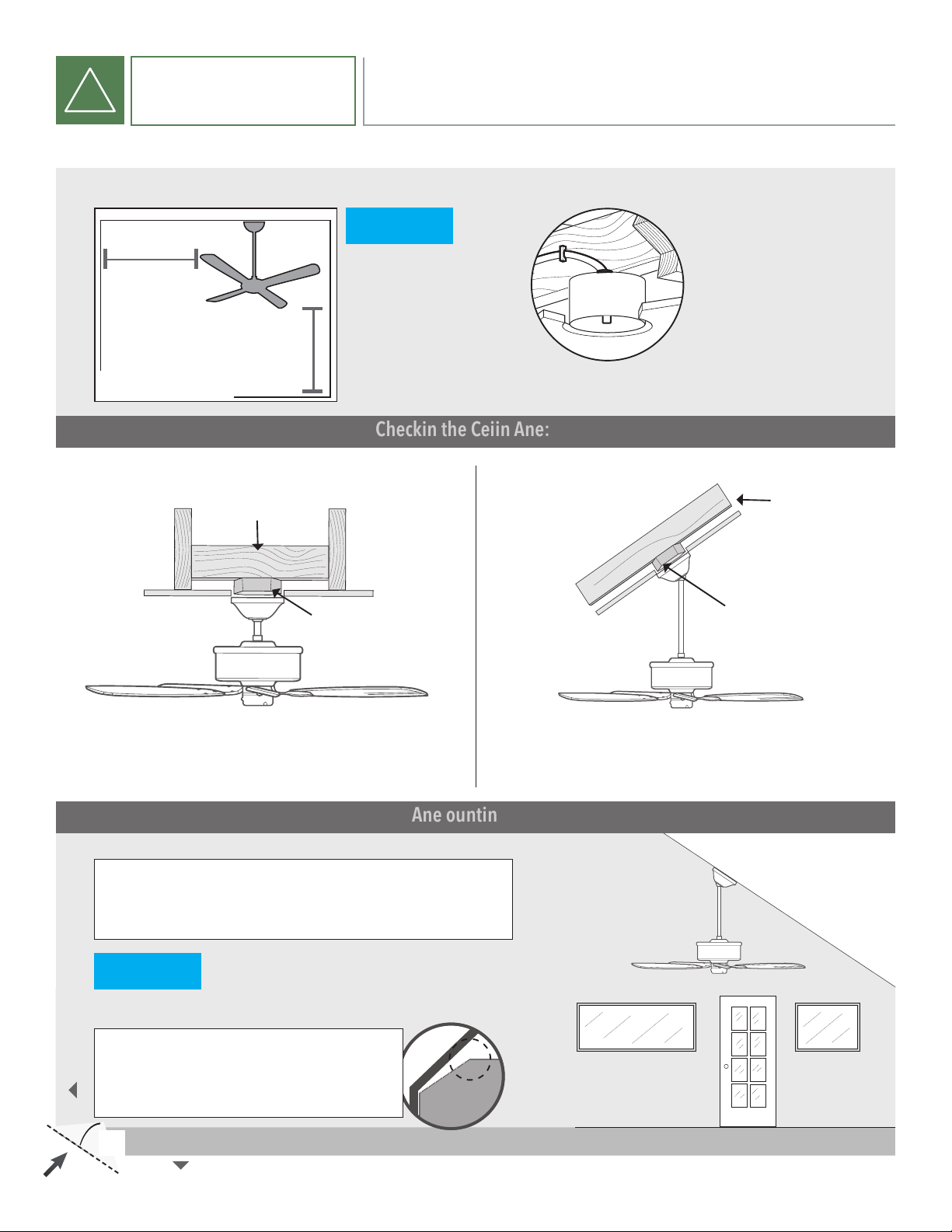
!CHOOSE THE RIGHT LOCATION
Checking the Ceiling Angle:
Angled Mounting
Checktheroomdimensions: Checktheoutletbox:
Youmustbeableto
securethefantobuilding
structureorfan-ratedoutlet
boxandclearlymarked
acceptableforfansupport
of70lbs(31.8kg)orless.
30 inches
frombladetipto
nearestwallor
obstruction 10 feet
frombottom
edgeof bladeto
the oor
CeilingOutlet
Box(required)
AngledMounting
If you have an angled or vaulted ceiling:
1. Youwillneedalongerdownrod.
Support
Structure
If you have a at ceiling:
1. Hangyourfanbyastandarddownrod.Fortallceilings
youmay needalongerdownrod.
SupportStructure
CeilingOutlet
Box(required)
StandardMounting
A little more information on Angled Mounting:
Foroptimumperformanceandappearance,alongerdownrodshouldbeused
withyourHunterceilingfanwheninstallingonhighorangledceiling.
Determining angle of ceiling:
Foldonthedottedline.Placelongedgeagaintsthewall.
Slidetowardstheceiling.Iftheguidetouchesthewall
butnottheceiling,yourceilingisgreaterthan34°.
Hunter Pro Tip:
CEILING
WALL
34°
Fancannotbemountedontoaceilingwithanangle
greaterthan34°
Ensurefansdistanceistwice
thediameterof thefanfrom
theairdischargelocations.
NOTICE
NOTICE
7
BEFORE YOU BEGIN FAN PLACEMENT
!
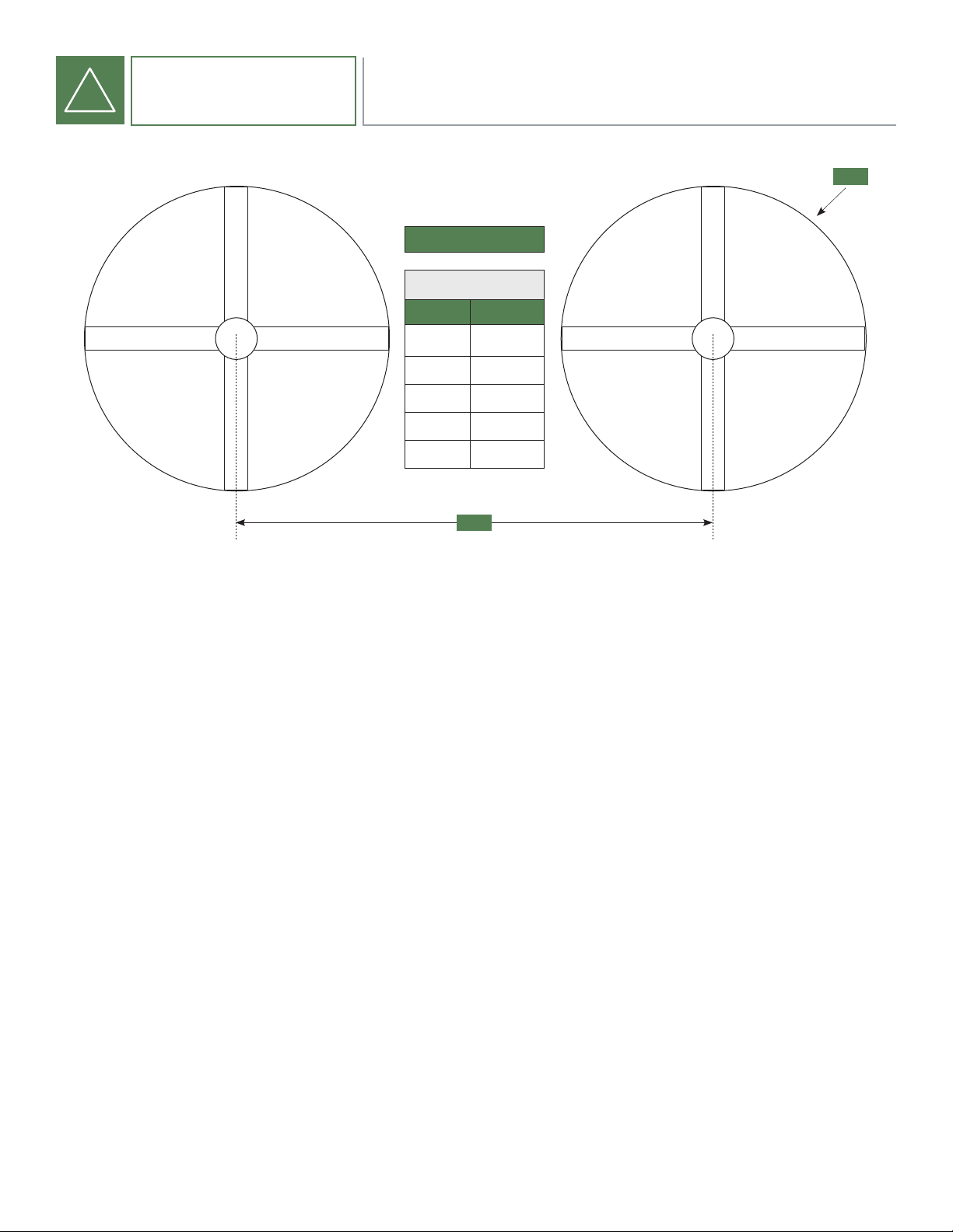
FAN PLACEMENT
FAN SPACING CHART
A
B
A
TRAK
A B
DIA MIN-MAX
8ft(96”) 20ft-32ft
7ft(84”) 18ft-28ft
6ft(72”) 16ft-24ft
5ft(60”) 14ft-20ft

8
BEFORE YOU BEGIN
!FAN PLACEMENT
ALWAYS MOUNT FAN SO THE BOTTOM EDGE OF BLADE TO THE FLOOR IS AT LEAST 10 FEET.
Always mount fans away from the following:
Sprinkler Systems
Prior to installing fans, review all codes applicable to sprinkler systems and fans to ensure code compliance and refer to NFPA 13: Fire
Sprinkler System Installation. In any installation where re sprinklers are present, the fan should not interfere with their operation.
• Fans should be located at least 3 feet below a sprinkler deector.
• Fansshouldbecenteredbetween4adjacentsprinklers.
It is your responsibility that the installation complies with the applicable codes.For assistance,please call ourTechnical Department at
1-844-591-FANS(3267),oremailusat:[email protected].
Walkways and Mezzanines
If the building has elevated walkways or mezzanines, mount the fans so that a person cannot reach the rotating blades in any way.
Positionfanssothatthetipsof thebladesareatleast5feetawayfromanyareawhereapersonmaybeabletoextendoutwardtoreach
them.
Lights and Skylights
Ifpossible,avoidmountingfansdirectlybelowlightsorskylightstoavoidanystrobeeffectcausedbymovingblades.
There should be a minimum of 2 feet between the blades and any light xture.
Air Discharge Locations
Fansshouldnotbelocateddirectlybeneathorinlinewithanyairdischarge.Thisincludesairconditioningunitsandevaporativecoolers.
Suchequipmentcanbeusedeffectivelyinconjunctionwithceilingfanshoweverthedischargeof theunitmustbelocatedoutsidethe
sweptareaof thefanandatadistanceof atleasttwotimesthediameter.
9
BEFORE YOU BEGIN PRE-INSTALLATION CHECKLIST
!
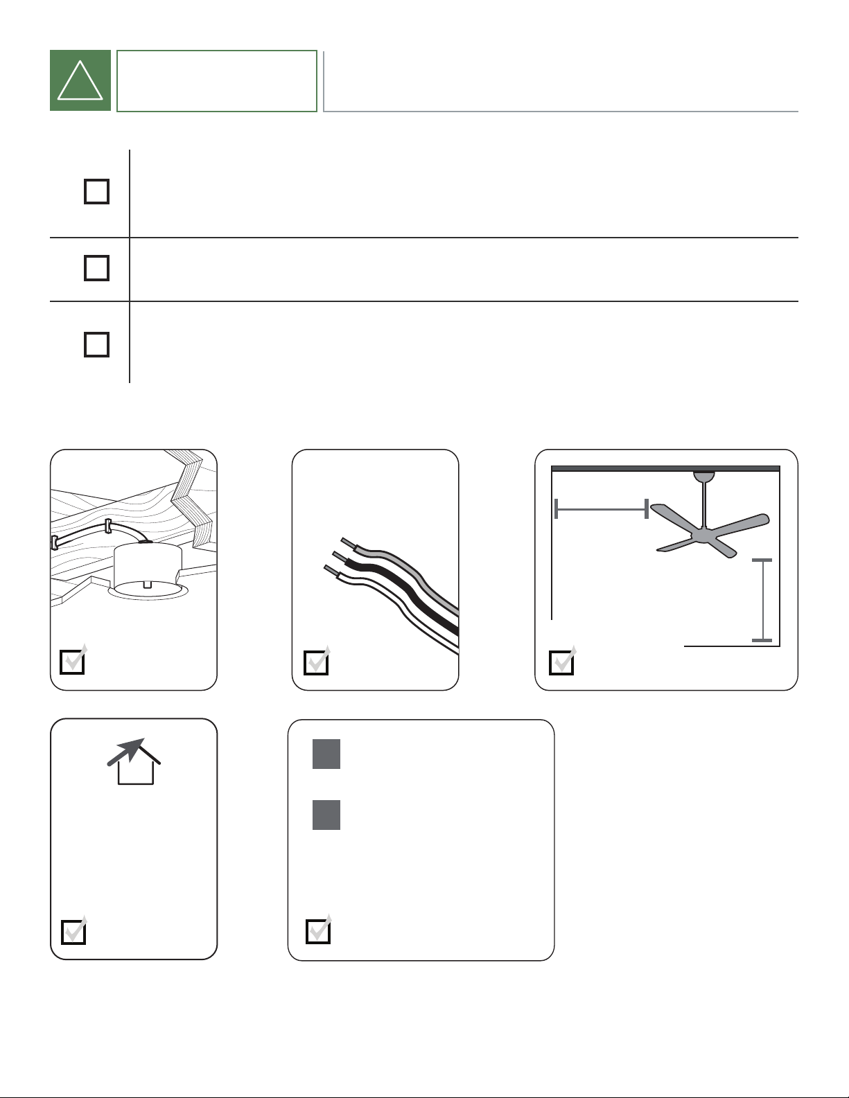
The location of the fan will allow for a minimum of 2 feet of blade clearance
from any obstruction and at least 10 feet of clearance above the oor.
If installing multiple fans, reference the fan placement chart for optimal spacing.
The control panel voltage markings (either 100-120VAC or 220-240VAC at 50/60Hz)
should match your buildings supply power.
Assesslocation
30 inches
frombladetipto
nearestwallor
obstruction 10 feet
frombottom
edgeofblade
to the oor
Knowyourwiring
Ifyouareunfamiliar
withwiring,usea
qualied electrician.
Mustbeabletosecure
thefantobuilding
structureorfan-rated
outletbox
Selectadownrodlength
1
2
Standard Downrod
forceilings12-14feethigh
Longer Downrod
forceilings14feetorhigher
Assessceilingangle
Maximumceilingangle
is34°.
10
BEFORE YOU BEGIN
!TOOLS NEEDED
Ladder Screwdrivers
1/2”/M4Wrench
x2
Included
RightAngledScrewdriver
AllenWrench BladeInstallationTool
Table of contents
Other Hunter Fan manuals

Hunter
Hunter 28079 Manual

Hunter
Hunter 28790 Instruction Manual

Hunter
Hunter DDI User manual

Hunter
Hunter 21327 User manual

Hunter
Hunter Builder Plus 53236 User manual

Hunter
Hunter 28496 Manual

Hunter
Hunter 42686-01 Instruction manual

Hunter
Hunter Regalia II User manual

Hunter
Hunter Presto User manual

Hunter
Hunter 99125 User manual

Hunter
Hunter 20552 Instruction manual

Hunter
Hunter 42609-01 Instruction manual

Hunter
Hunter Protos User manual

Hunter
Hunter Lake Cottage Instruction manual

Hunter
Hunter Dempsey User manual

Hunter
Hunter Gallery Edition User manual

Hunter
Hunter Savoy Instruction manual

Hunter
Hunter 28698 User manual

Hunter
Hunter 23488 Instruction Manual

Hunter
Hunter 42884-01 Instruction manual