Hunter 42890-01 Instruction manual

Type A ModelsType A ModelsType A Models
Form# 42890-01
20100218
©2010 Hunter Fan Co.
For Your Records and
Warranty Assistance
For reference, also attach your receipt or a copy
of your receipt to the manual.
__________________________________________
Model Name
__________________________________________
Model No.
__________________________________________
Catalog No.
__________________________________________
Date Purchased
__________________________________________
Where Purchased
English Español
Owner’s Guide and Installation Manual

2
42890-01 • 02/18/10 • Hunter Fan Company
Table of Contents
1 • Getting Ready ...................................................4
2 • Installing the Ceiling Plate..........................5
3 • Assembling the Fan .......................................6
4 • Hanging and Wiring the Fan.....................7
5 • Installing the Canopy and Canopy
Trim Ring..............................................................8
6 • Assembling the Blades.................................9
7 • Completing Your Installation With
or Without a Light Fixture....................... 10
8 • Operating and Cleaning
Your Ceiling Fan............................................. 14
9 • Troubleshooting ........................................... 15
© 2010 Hunter Fan Company
Your new Hunter® ceiling fan is an addition to your home or oce that
will provide comfort and performance for many years. is installation
and operation manual gives you complete instructions for installing
and operating your fan.
We are proud of our work. We appreciate the opportunity to supply
you with the best ceiling fan available anywhere in the world.
Before installing your fan, for your records and warranty assistance,
record information from the carton and Hunter nameplate label
(located on the top of the fan motor housing).
Cautions and Warnings
•READ THIS ENTIRE MANUAL CAREFULLY BEFORE BEGINNING
INSTALLATION. SAVE THESE INSTRUCTIONS.
• Use only Hunter replacement parts.
• To reduce the risk of personal injury, attach the fan directly to the
support structure of the building according to these instructions,
and use only the hardware supplied.
• To avoid possible electrical shock, before installing your fan,
disconnect the power by turning o the circuit breakers to the
outlet box and associated wall switch location. If you cannot lock
the circuit breakers in the o position, securely fasten a prominent
warning device, such as a tag, to the service panel.
• All wiring must be in accordance with national and local electrical
codes and ANSI/NFPA 70. If you are unfamiliar with wiring, use a
qualied electrician.
• To reduce the risk of personal injury, do not bend the blade
attachment system when installing, balancing, or cleaning the fan.
Never insert foreign objects between rotating fan blades.
• To reduce the risk of re, electrical shock, or motor damage, do not
use a solid-state speed control with this fan. Use only Hunter speed
controls.
Welcome
3
42890-01 • 02/18/10 • Hunter Fan Company
Mounting and Optional Accessories
Understanding Mounting
Hunter’s patented mounting system provides you maximum ease in
installing your fan. is fan was designed to be mounted only on at
ceilings and can be used on ceilings less than 8 feet high.
Considering Optional Accessories
Consider using Hunter’s optional accessories, including a wall-mounted
or remote speed control. To install and use the accessories, follow
the instructions included with each product. For quiet and optimum
performance of your Hunter fan, use only Hunter speed controls.
Low Profile Mounting ts close to the
ceiling, recommended for ceilings less
than 8 feet high
Support Brace
Low Prole
Mounting
Style
Ceiling
Outlet Box
CAUTION: To reduce the risk of
personal injury, attach the fan directly
to the support structure of the building
according to these instructions, and use
only the hardware supplied.

4
42890-01 • 02/18/10 • Hunter Fan Company
1 • Getting Ready
To install a ceiling fan, be sure you can do the following:
• Locate the ceiling joist or other suitable support in ceiling.
• Drill holes for and install wood screws.
• Identify and connect electrical wires.
• Lift 40 pounds.
If you need help installing the fan, your Hunter fan dealer can direct
you to a licensed installer or electrician.
Gathering the Tools
You will need the following tools for installing the fan:
• Electric drill with 9/64” bit
• Standard screwdriver (magnetic tip recommended)
• Phillips-head screwdriver (magnetic tip recommended)
• Wrench or pliers
• Ladder (height dependent upon installation site)
Checking Your Fan Parts
Carefully unpack your fan to avoid damage to the fan parts. Refer to
the included Parts Guide. Check for any shipping damage to the motor
or fan blades. If any parts are missing or damaged, contact your Hunter
dealer or call Hunter Technical Support Department at 888-830-1326.
Preparing the Fan Site
Before you begin installing the fan, follow all the instructions in
the pullout sheet called “Preparing the Fan Site.” Proper ceiling fan
location and attachment to the building structure are essential for
safety, reliable operation, maximum eciency, and energy savings.
Installing Multiple Fans?
If you are installing more than
one fan, keep the fan blades and
blade irons (if applicable) in sets,
as they were shipped.

5
42890-01 • 02/18/10 • Hunter Fan Company
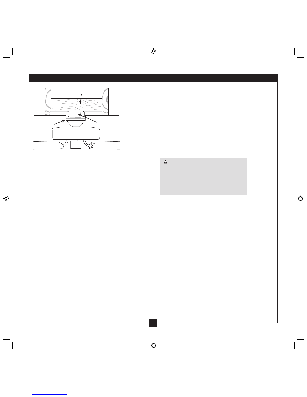
2 • Installing the Hanger Bracket
Steps 2-4 – 2-6
CAUTION: To avoid possible electrical shock, before installing your fan,
disconnect the power by turning o the circuit breakers to the outlet box
and associated wall switch location. If you cannot lock the circuit breakers
in the o position, securely fasten a prominent warning device, such as a
tag, to the service panel.
2-1. Drill two pilot holes into the wood support structure through the
outermost holes in the outlet box. e pilot holes should be 9/64”
in diameter.
2-2. read the lead wires from the outlet box down through the hole
in the middle of the ceiling plate.
2-3. Align the slotted holes in the ceiling plate with the pilot holes you
drilled in the wood support structure.
2-4. Place a at washer on each of the two 3” wood screws and pass
the screws through the slotted holes in the ceiling plate into the
pilot holes you drilled.
Tighten the screws into the 9/64” pilot holes; do not use lubricants
on the screws. Do not over tighten.
Ceiling
Plate
Flat Washer
3” Wood Screw

6
42890-01 • 02/18/10 • Hunter Fan Company
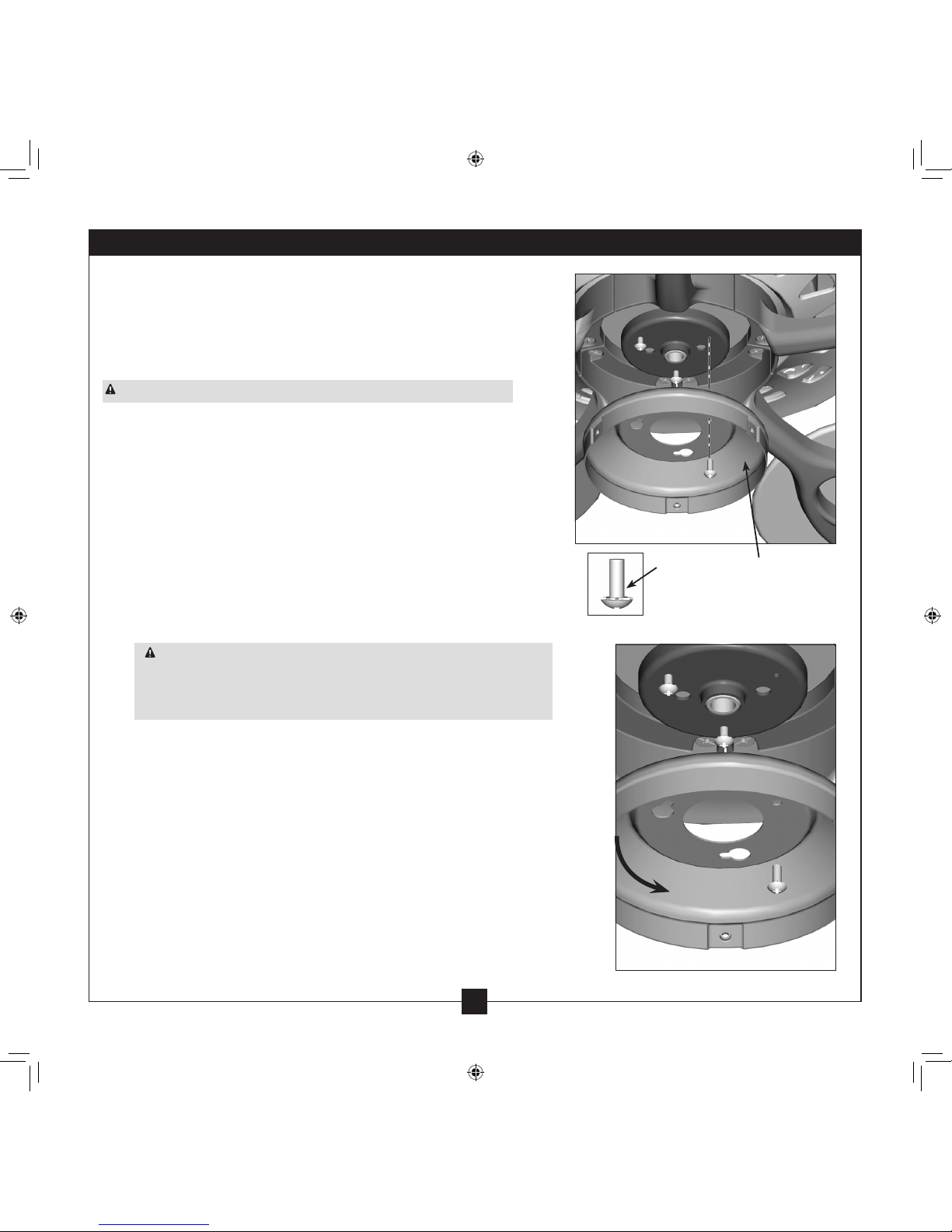
3 • Assembling and Hanging the Fan
WARNING: Fan may fall if not assembled as directed in these
installation instructions.
3-1. Lift the motor assembly and hook the three tabs over the handles,
one at a time.
Step 3-1 Handle
Tab

7
42890-01 • 02/18/10 • Hunter Fan Company
Dual Switch Wiring
Single Switch Wiring
4 • Wiring the Fan
All wiring must be in accordance with national and local electrical
codes and ANSI/NFPA 70. If you are unfamiliar with wiring, use a
qualified electrician.
Wall switches are not included. Select an acceptable general-use switch
in accordance with national and local electrical codes.
4-1. Before attempting installation, make sure the power is still o.
4-2. To connect the wires, hold the bare metal leads together and place
a wire connector over them, then twist clockwise until tight. For
all these connections use the wire connectors provided.
4-3. Connect the bare or green ground wire (grounded) from the
ceiling to the green ground wire (grounded) from the ceiling plate
and the green ground wire from the fan.
4-4. Connect the white wire (ungrounded) from the ceiling to the
white wire (ungrounded) from the fan.
4-5. Connect the remaining wires as follows:
Dual Switch Wiring:
• e black wire (ungrounded) from the ceiling to the black wire
(ungrounded) from the fan
• e black/white wire (ungrounded) from the fan to the wire
(ungrounded) for the wall switch
Single Switch Wiring:
• e black wire (ungrounded) from the ceiling to the black
(ungrounded) and the black/white wire (ungrounded) from
the fan
CAUTION: Be sure no bare wire or wire strands are visible after
making connections.
4-6. Turn the splices upward and push them carefully back through the
ceiling plate into the outlet box.
4-7. Spread the wires apart, with the grounded wires on one side of
the outlet box and the ungrounded wires on the other side of the
outlet box.

8
42890-01 • 02/18/10 • Hunter Fan Company
5-1. Place the fan housing over the motor.
5-2. Align the holes in the fan housing with the holes in the
ceiling plate.
5-3. Partially install each canopy screw into the holes in the
fan housing and into the ceiling plate until all holes are
aligned. Securely tighten all screws.
Steps 5-1 – 5-3
Canopy Screw
Canopy
Screw
Canopy
Housing
5 • Installing the Motor Housing

9
42890-01 • 02/18/10 • Hunter Fan Company
9
6 • Assembling the Blades
Hunter fans use several styles of fan blade irons (brackets that hold the
blade to the fan).
6-1. Your fan may include blade grommets. If your fan has grommets,
insert them by hand into the holes on the blades.
6-2. Attach each blade to a blade iron using three blade assembly
screws. If you used grommets, the blades may appear slightly loose
after screws are tightened. is is normal.
6-3. Remove the blade mounting screws and rubber shipping bumpers
from the motor. Note: Some blade mounting screws are installed
in the motor to secure shipping blocks.
6-4. For each blade, insert one blade mounting screw through the
blade iron, and attach lightly to the fan. Insert the second blade
mounting screw, then securely tighten both mounting screws.
Step 6-1 (Detail)
Grommet
Blade
Mounting
Screw
Steps 6-1 – 6-2
Step 6-4
Note: e blades on this fan have been treated
with Hunter’s Dust Armor protection, making
the blades less likely to attract dust and dirt.
Use a dry or slightly damp lint free cloth to
clean the blades. Do not use a furniture polish
or any other cleaners that leave any residue, as
they will damage the protective Dust Armor
on the blades.
Blade Assembly
Screws
Use with grommet
Use without grommet
10
42890-01 • 02/18/10 • Hunter Fan Company
7 • Completing Your Installation With or Without a Bowl Light Fixture
Your Hunter fan comes with an integrated light xture assembly and
an optional switch housing cap and plug button. is feature gives
you the option of installing the fan with OR without the included light
xture. e steps below direct you whether or not you are installing a
light xture.
WARNING: Use only the light xture supplied with this fan model.
7-1. To attach the upper switch housing, partially install two housing
assembly screws into the switch housing mounting plate.
7-2. Feed the upper plug connector through the center opening of the
housing.
7-3. Align the keyhole slots in the housing with the housing assembly
screws.
7-4. Turn the housing counterclockwise until the housing assembly
screws are rmly situated in the narrow end of the keyhole slots.
Install the remaining screw into the housing. Tighten all three
screws rmly.
CAUTION: Make sure the upper switch housing is securely
attached to the switch housing mounting plate. Failure to properly
attach and tighten all three assembly screws could result in the
switch housing and light xture falling.
7-5. If you want to install the light fixture, proceed with step 7-6
now.
If you do not want to install the light fixture, you need to
uninstall it now. See “Uninstalling the Light Fixture” on step 7-15.
Once you have uninstalled the light xture, continue with step 7-6.
Steps 7-1 – 7-3
Housing
Assembly
Screw
Upper
Switch
Housing
This manual suits for next models
1
Table of contents
Other Hunter Fan manuals

Hunter
Hunter 21970 Manual

Hunter
Hunter 41953-01 User manual

Hunter
Hunter Antero 52128 User manual

Hunter
Hunter 51844 User manual

Hunter
Hunter 28480 Manual

Hunter
Hunter 28461 Manual

Hunter
Hunter Cassius User manual

Hunter
Hunter Abernathy User manual

Hunter
Hunter Jesse Instruction manual

Hunter
Hunter Minimus 51431 User manual

Hunter
Hunter 28673 Manual

Hunter
Hunter Devon Park User manual

Hunter
Hunter Hunter Ceiling Fan User manual

Hunter
Hunter 28682 Manual

Hunter
Hunter Allendale LED 53302 User manual

Hunter
Hunter Bennett Series User manual

Hunter
Hunter Crossfield 50242 User manual

Hunter
Hunter 21617 Manual

Hunter
Hunter Tailwind User manual

Hunter
Hunter 21978 User manual


