HULTDINS SuperSaw 650S User manual

Installation manual
S/N 053-0038 & up
SuperSaw 650S

2014– HULTDIN SYSTEM AB.
This publication applies to the following models:
SuperSaw 650S S/N 053-0038 & up
This publication contains instructions for the installation and maintenance of the SuperSaw 650S grapple saw units. The
instructions cover general information, procedures and specifications applicable to this grapple saw. If doubt should arise
concerning the validity of the instructions please consult the nearest dealer for more detailed information.
Illustrations, technical information and specifications were, as far as we have been able to judge, correct at the time of print.
However, we reserve the right to, without prior notice, revise specifications, instructions, equipment, etc. as a result of
ongoing product improvement activities.
No part of this publication may without approval of HULTDIN SYSTEM AB be translated, reproduced, stored or
transmitted electronically, mechanically, photographically or in another way not specified here.
Even if all conceivable measures have been taken to make the contents as complete as possible, HULTDIN SYSTEM AB
takes no responsibility for possible damages that may arise as a result of the instructions not being followed or improper use
of the product
Important!
The parts and components used in HULTDIN SYSTEM AB’s products are specifically chosen. Therefore original
spare parts are always the best alternative in a possible need of repairs or upgrading.
All service and repairs should be carried out by qualified service personnel or an authorized repair shop with suitable tools
and lifting devices.
This publication is published by: HULTDIN SYSTEM AB
Skolgatan 12
SE-930 70 MALÅ
Sweden

en_ss650sTOC.fm SuperSaw 650S
CONTENTS
Contents Page Contents Page
Safety instructions.................................................... 4
General safety....................................................... 4
Meaning of safety messages................................. 4
Operational Safety................................................ 5
Chain shot hazard................................................. 5
Operator and bystander safety........................ 5
Maintenance safety............................................... 6
Welding........................................................... 6
Modifying the equipment............................... 6
Product description.................................................. 7
Main parts, Grapple saw ...................................... 7
Lubrication oil tank.............................................. 8
Adjustment valves, Grapple saw.......................... 9
Hydraulic pressure test points............................ 10
SuperCut 300...................................................... 11
Labeling.............................................................. 12
Technical Data........................................................ 13
SuperSaw 650S - 40cc ....................................... 13
Rotator bracket HD............................................ 14
SuperGrip TL mtg. bracket................................ 15
Special tools....................................................... 16
Hydraulic diagram SuperSaw 650S................... 18
Functional description........................................... 19
Chain lubrication system.................................... 19
Installation.............................................................. 20
Where to install the grapple saw? ...................... 20
Installing HD rotator bracket ............................. 21
Hydraulic installation......................................... 22
SuperGrip TL installation .................................. 23
Hydraulic installation......................................... 24
Initial upstart.......................................................... 25
Saw motor upstart .............................................. 25
Adjusting saw bar feed out pressure .................. 26
Adjusting saw bar retraction .............................. 26
Adjusting chain tension pressure ....................... 27
Bleeding the chain tension system..................... 27
Procedures .............................................................. 28
Replacing saw chain........................................... 28
Replacing saw bar.............................................. 29
Replacing bar holder .......................................... 30
Replacing drive sprocket.................................... 31
Refilling chain lubrication oil ............................ 32
Maintenance instructions...................................... 33
Regular maintenance.......................................... 33
Daily maintenance........................................ 33
Lubrication ................................................... 34
The first month of operation .............................. 34
Fasteners....................................................... 34

SAFETY INSTRUCTIONS
4Safety instructions en011301_sc.fm
Safety instructions
General safety
• This page describes important safety instructions,
which the operator should have a good
knowledge of before the equipment is used.
• This product should only be used by operators
with proper knowledge and training.
• The owner and the operator are responsible for
following all safety regulations and that the
machine is safely equipped.
• The owner and the operator are responsible for
following National and local laws, regulations
and other instructions when using the product.
• The owner and the operator are responsible for
replacing damaged parts and/or unreadable
warning signs.
• The manual should be available at all times so
that the operator is able to follow safety
regulations and the procedures of maintenance
activities.
Meaning of safety messages
Danger!
Danger indicates a hazard with a high level of risk
which, if not avoided, will result in death, serious
injury and/or serious property damage.
Warning!
Warning indicates a hazard with a medium level of
risk which, if not avoided, could result in death,
serious injury and/or serious property damage.
Caution!
Caution indicates a hazard with a low level of risk
which, if not avoided, could result in minor or
moderate injury and/or property damage

SAFETY INSTRUCTIONS
en011301_sc.fm Safety instructions 5
Operational Safety
• Check the unit for damages at the beginning of
each shift.
• Make sure that the hydraulic pressure in the
grapple cylinder is adjusted according to the
specifications. If the pressure is too high, the unit
will be overloaded, which could cause a
structural failure, resulting in injury and/or
property damage.
• When operating this equipment ensure all
unauthorized persons remain at least 90 meters
clear of the machine.
• The operator must immediately evict
unauthorized persons who are in the danger zone
or are heading towards the danger zone
• Training or demonstration of this equipment
should be performed from an operator´s cab
approved by national regulations. Observers
should always remain at least 90 meters.
• Keep all windows and doors securly closed when
operating.
Chain shot hazard
Operator and bystander safety
Because of the high speeds, high stress, heavy loads, wear
factors and varying levels of repair and maintenance given
to saw-chain based machines, there is a possibility that
chain or chain pieces can be thrown from the machine at
high speed and enormous energy. Operators and
bystanders are exposed to a risk of serious injury.
Machines should be designed with appropriate guards and
shields, and care should be taken to minimize the exposure
of users and bystanders to the cutting plane of the saw.
• There is risk of seriousinjury or death to machine
operators and bystanders from “Chain Shot”,
which is the high-speed ejection of chain parts
that can occur in the event of a derailed or a
broken chain. For maximum protection, machines
should be equipped with an energy-absorbing
chain shot guard.
• Always use High Speed saw chains with 3/4”
pitch saw units.
90 meters

SAFETY INSTRUCTIONS
6Safety instructions en011301_sc.fm
Maintenance safety
• The machine's condition must be checked
regularly, daily inspections shall be performed
and any deficiencies must be corrected. The
machine shall be maintained in such condition
that the operator or other persons are not exposed
to danger or accidents.
• Never commit any service on the equipment
without proper knowledge. All service and
repairs in electrical and hydaulical systems
should be carried out by qualified personnel only.
• Repair any damages immediate when discovered.
Do not use the equipment until any damages are
rectified.
• Before performing any maintenance or service
work, lower the unit to the ground and shut off
the engine. Turn off any master shut-offs and do
not allow personnel in the cab.
• When working on the saw chain always ensure
the engine is shut off and wear safety gloves to
prevent injuries. Remove the saw chain when
making any adjustments or servicing the saw unit
• Use safety glasses and protective gloves when
servicing the equipment. Hydraulic oil or
lubricants in contact with skin or eyes may cause
irritations or allergies.
• Use hard hat and safety boots when servicing the
equipment. Leakage of hydraulic oil or lubricants
will increase the risk of slipping or falling.
• The unit has sharp edges. Use proper wrenches
and protective gloves when working on the unit.
• Hydraulic hoses and adapters may be pressurized
even with the engine shut off. Loosen any parts
with caution.
• Always make sure that the system is
depressurized before committing any service on
the equipment.
• Always secure movable parts mechanically
before any hydraulic hose is loosened.
• Never try to stop a leakage in the hydraulic
system with you hand. Pressurized hydraulic oil
can be injected under the skin and cause death or
severe damage.
Welding
In case of a structural repair of the equipment, when
welding may be needed, consult the dealer for
recommended instructions.
When welding on the equipment the following steps
must be taken:
• Make sure that fire-extinguishing equipment is
available.
• Clean the area around the welding area to
eliminate any fire hazard.
• Connect the ground wire so the welding current
does not pass over any bushings.
• Place the ground wire as close to the welding area
as possible.
• When welding close to bushings, dissassemble
the bushings asthey are made of a plastic
compound-material which high temperatures may
damage.
Modifying the equipment
It is not approved to:
• Modify the equipment without the consent of
HULTDIN SYSTEM AB.
• Alter the function of the equipment without the
consent of HULTDIN SYSTEM AB.
• Use spare parts other than original HULTDINS
parts.

PRODUCT DESCRIPTION
en011102a_ss650.fm SuperSaw 650S 7
Product description
Main parts, Grapple saw
The SuperSaw 650S grapple saw consists basically of a frame, a saw unit and a
hydraulic system. The illustration shows the location of the main parts.
Fig. 1 Main parts SuperSaw 650S
1Frame
2 Saw motor cover
3 Cover plate
4 Adjusting valve for chain tension pressure
5 Saw motor manifold
6 Saw unit
7 Saw motor
8 Accumulator for saw motor case drain
9 Air tank for saw bar retraction
10 Air nippel for air-pressure adjustment
11 Saw bar
12 Saw chain
12
3
5
6
7
8
910
11
12
4
PRODUCT DESCRIPTION
8 SuperSaw 650S en011102d_ss650.fm
Product description
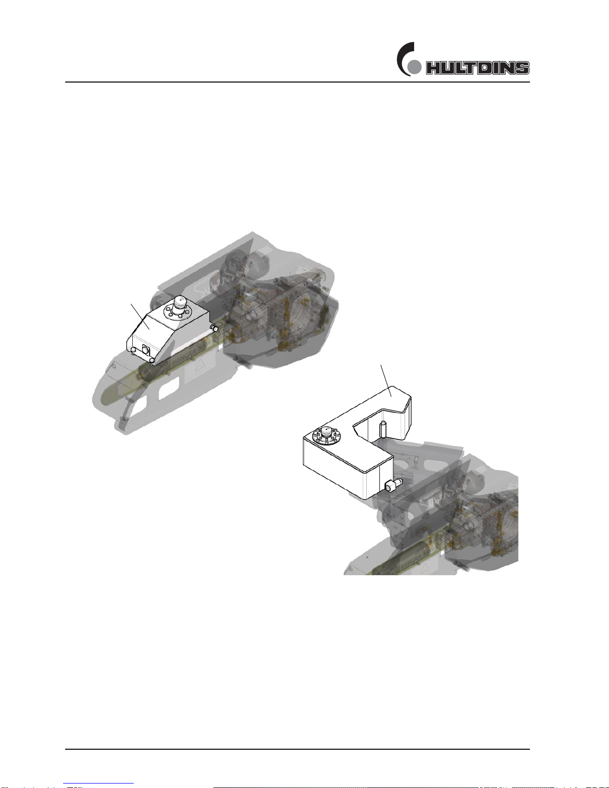
Lubrication oil tank
The SuperSaw 650S grapple saw can be equipped with two different lubrication oil
tanks. One integrated 6,1 litre tank, or an external 26,5 litre tank. The design and
placement of the two different tank is shown below.
Fig. 2 Lubrication oil tanks, SuperSaw 650S
1 6,1 litre oil tank
2 26,5 litre oil tank
1
2

PRODUCT DESCRIPTION
en011102b_ss650.fm SuperSaw 650S 9
product description
Adjustment valves, Grapple saw
The SuperSaw 650S grapple saw has the following adjustment valves. The location
of the valves shows on the illustration.
ill. 3 Adjustment valves
1 Pressure regulating valve for saw chain tension pressure
2 Air nipple for saw bar retraction adjustment
1
2

PRODUCT DESCRIPTION
10 SuperSaw 650S en011402c_ss650.fm
product description
Hydraulic pressure test points
The SuperSaw 650S grapple saw has four different hydraulic pressure test points,
as shown on the following illustration.
ill. 4 Hydraulic pressure test points
1 Test point for saw bar feed out pressure
2 Test point for chain tension pressure
3 Test point for saw motor case drain pressure
4 Test point for saw motor return line pressure
1
2
3
4
Table of contents
Other HULTDINS Saw manuals


