HP A6604 User manual

HP A6604 and A6608 Router
Installation Manual

About This Manual
Organization
HP A6604/A6608 Routers Installation Manual is organized as follows:
Chapter Contents
1 Router Overview Briefly introduces the product specifications, as well as
the features and applications of the HP A6604/A6608.
2 Preparing for Installation
Describes the requirements on installation site, the
safety recommendations before and during installation,
and the required tools.
3 Installing the Router
Introduces how to install the A6604/A6608, as well as
how to connect the power cable, console cable, AUX
port cable, Ethernet cable, interface card and interface
module cable.
4 Starting and Configuring the Router
Helps you get familiar with the basic knowledge of how
to boot and configure the HP A6604/A6608, including
device startup, power-on, and initialization of system
files, and so on.
5 Maintaining Software
Introduces how to maintain the software of the HP
A6604/A6608, including upgrading the software and
updating the configuration files.
6 Maintaining Hardware Introduces how to maintain the hardware of the HP
A6604/A6608.
7 Troubleshooting
Describes some problems that may occur during
installation and startup of the router and how to solve
them.
Conventions
The manual uses the following conventions:
Command conventions
Convention Description
Boldface The keywords of a command line are in Boldface.
italic Command arguments are in italic.
[ ] Items (keywords or arguments) in square brackets [ ] are optional.
{ x | y | ... } Alternative items are grouped in braces and separated by vertical bars. One is
selected.
[ x | y | ... ] Optional alternative items are grouped in square brackets and separated by
vertical bars. One or none is selected.

Convention Description
{ x | y | ... } * Alternative items are grouped in braces and separated by vertical bars. A
minimum of one or a maximum of all can be selected.
[ x | y | ... ] * Optional alternative items are grouped in square brackets and separated by
vertical bars. Many or none can be selected.
&<1-n> The argument(s) before the ampersand (&) sign can be entered 1 to n times.
# A line starting with the # sign is comments.
GUI conventions
Convention Description
Boldface Window names, button names, field names, and menu items are in Boldface.
For example, the New User window appears; click OK.
>Multi-level menus are separated by angle brackets. For example, File >
Create >Folder.
Convention Description
< > Button names are inside angle brackets. For example, click <OK>.
[ ] Window names, menu items, data table and field names are inside square
brackets. For example, pop up the [New User] window.
/Multi-level menus are separated by forward slashes. For example,
[File/Create/Folder].
Symbols
Convention Description
Means reader be extremely careful. Improper operation may cause bodily
injury.
Means reader be careful. Improper operation may cause data loss or damage
to equipment.
Means an action or information that needs special attention to ensure
successful configuration or good performance.
Means a complementary description.
Means techniques helpful for you to make configuration with ease.
Related Documentation
In addition to this manual, each HP A6600 Routers documentation set includes the following:
Manual Description
HP A6600 Routers User Manual It is a guide for the user to perform the operations
correctly. It is organized into the parts of access, IP
services, IP routing, MPLS, VPN, QoS, security,

Manual Description
system, multicast, and OAA.
It also gives the user a detailed description of the
operating commands. It is organized into the parts of
access, IP services, IP routing, MPLS, VPN, QoS,
security, system, multicast, and OAA, as well as a
command index.
HP A6600 Routers Interface Card and Interface
Module Manual
This manual introduces all kinds of interface modules
that SR6600 routers support, the means of
connection the interface cables and the interface
module purchase guide.
Low-End and Mid-Range Series Routers Cable
Manual This manual introduces all cable pinouts available
with low-end and mid-range series routers.
Environmental Protection
This product has been designed to comply with the requirements on environmental
protection. For the proper storage, use and disposal of this product, national laws and
regulations must be observed.

1Router Overview
Introduction
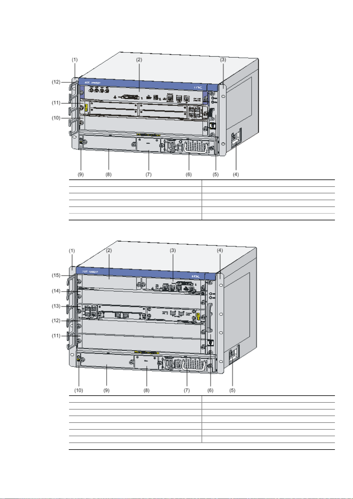
The HP A6604 and A6608 routers are high-performance service routers developed by Hewlett
Packard (hereinafter referred to as HP) for enterprise networks and carrier-edge access. The
A6604 and A6608 adopt two RPE-X1s modules as the main processing units (MPUs), two
power modules, and a distributed modular architecture. Abundant optional modules are
available so that the two service routers can have a powerful processing capability and support
flexible configuration to fully meet the requirements of enterprise networks and carrier networks.
The A6604 and A6608 can work at the core layer of small- and medium-sized enterprise
networks or at the distribution layer and core layer of large-sized enterprise networks. They can
also work at the access layer of carrier networks or large enterprise networks.
With the high-performance microprocessor technology, advanced hardware architecture and HP
proprietary Comware V5 platform, the A6604 and A6608 provide high service processing
capabilities, good service scalability, and high reliability. In addition, the A6604 and A6608 can
work together with other HP network devices to provide full network solutions for carriers and
departments in electric power, finance, tax, public security, railway and education, as well as for
medium- and large-sized enterprises. The full compliance with national and international
standards ensures the interoperability with the products of other manufacturers at different
layers.
The A6604 and A6608 support high-speed interface modules (HIMs) and provide a bus
processing capability of up to 10 Gbps, which can meet the high-speed performance
requirements of users. In addition, the A6604 and A6608 are compatible with some multi-
functional interface modules (MIMs) of the HP AR/MSR series routers to guarantee the smooth
upgrade from narrowband access to broadband access, improve the competitiveness, and
protect existing investments. For easy description, the term “device” is used throughout this
document to refer to any A6604 or A6608 router if not otherwise specified.
You can configure MPUs and flexible interface platforms (FIPs) on the A6604 and A6608 as
needed. Table 1-1 describes MPUs' support for FIPs on the A6604 and A6608.
Table 1-1 MPUs' support for FIPs
MPU FIP-100 FIP-110 FIP-200 FIP-210
RPE-X1 Supported Supported Supported Supported
RSE-X1 Not supported Supported Not supported Supported

The A6604 and A6608 support two types of MPUs, route processing engine (RPE) and route
switch engine (RSE).
To facilitate description, the term "FIP" is used throughout this document to refer to the FIP-
100, FIP-110, FIP-200, and FIP-210 if not otherwise specified.
The FIP-100 and FIP-110 support MIMs only.
The FIP-200 and FIP-210 support MIMs, HIMs, and HIM/MIM intermixing.
For details about the slot arrangement, refer to Chapter 2 "Arranging Slots and Numbering
Interfaces."
For details about installation and removal of HIMs and MIMs, refer to Chapter 4 "Installing the
Router.”
Physical Description
Front View
Figure 1-1 Front view of the A6604 (configured with an RPE-X1)
(1) Left mounting bracket (2) MPU slot (Slot 1)
(3) RPE-X1 (Slot 0) (4) Right mounting bracket
(5) Chassis handle (6) Fan tray
(7) AC power module (PWR 1) (8) PoE power module (reserved PoE slot)
(9) Power module (PWR 2) (10) ESD socket and silkscreen
(11) FIP slot (Slot 3) (12) FIP-200 (Slot 2)
(13) Cable management bracket

Figure 1-2 Front view of the A6604 (configured with an RSE-X1)
(1) Left mounting bracket (2) RSE-X1 (Slot 1)
(3) Right mounting bracket (4) Chassis handle
(5) Fan tray (6) AC power module (PWR 1)
(7) PoE power module (reserved PoE slot) (8) Power module (PWR 2)
(9) ESD socket and silkscreen (10) FIP slot (Slot 3)
(11) FIP-210 (Slot 2) (RSE-X1 compatible) (12) Cable management bracket
Figure 1-3 Front view of the A6608 (configured with an RPE-X1)
(1) Left mounting bracket (2) MPU slot (Slot 1)
(3) RPE-X1 (Slot 0) (4) Right mounting bracket
(5) Chassis handle (6) Fan tray
(7) AC power module (PWR 1) (8) PoE power module (reserved)
(9) Power module (PWR 2) (10) ESD socket and silkscreen
(11) FIP slot (Slot 5) (12) FIP slot (Slot 4)
(13) FIP slot (Slot 3) (14) FIP slot (Slot 2)
(15) Cable management bracket

Figure 1-4 Front view of the A6608 (configured with an RSE-X1)
(1) Left mounting bracket (2) RPE-X1 (Slot 1)
(3) Right mounting bracket (4) Chassis handle
(5) Fan tray (6) AC power module (PWR 1)
(7) PoE power module (reserved PoE slot) (8) Power module (PWR 2)
(9) ESD socket and silkscreen (10) FIP slot (Slot 5)
(11) FIP slot (Slot 4) (12) FIP-210 (Slot 3)
(13) FIP slot (Slot 2) (RSE-X1 compatible) (14) Cable management bracket
Currently, the device does not support power over Ethernet (PoE).
Rear View
Figure 1-5 Rear view of the A6604
(1) Warning label (2) Handle on the rear chassis panel

(3) Upper slide rail for the air filter (optional) (4) Air filter (optional)
(5) Lower slide rail for the air filter (optional) (6) Chassis handle
(7) Weight-bearing warning label (50 kg or 110.23 lb)
(8) Grounding screw and sign (9) Vents
Figure 1-6 Rear view of the A6608
(1) Warning label (2) Handle on the rear chassis panel
(3) Upper slide rail for the air filter (4) Air filter (optional)
(5) Lower slide rail for the air filter (6) Chassis handle
(7) Weight-bearing warning label (50 kg or 110.23 lb)
(8) Grounding screw and sign (9) Vents
Do not hold the handle indicated by (2) in Figure 1-5 on the rear chassis panel to move the
chassis because it is designed for the convenience of the rear chassis panel removal, but not
for bearing the chassis weight.
System Specifications
Dimensions, Weight and LPU Slots
Table 1-2 Dimensions, weight and LPU slots
Item Specification
A6604 A6608
Dimensions without feet and
mounting brackets (H × W × D) 220 × 436 × 480 mm (8.66 ×
17.17 × 18.90 in.) 308 × 476 × 436 mm (12.13 ×
18.74 × 17.17 in.)
Weight (full configuration) 38 kg (83.77 lb) 50 kg (110.23 lb)
LPU slots 2 4

Power Modules
Table 1-3 Power module specifications
Item Specification
Rated voltage range AC powered: 100 VAC to 240 VAC; 50 Hz or 60 Hz
DC powered: –48 VDC to –60 VDC
Maximum input current AC powered: 10 A
DC powered: 25 A
Maximum power provided by one power module 650 W
Physical dimensions (H × W × D) 40 × 140 × 354 mm (1.57 × 5.51 ×13.94 in.)
Power module slots Two power module slots are provided. The power
modules must have the same specifications.
Power consumption range A6604: 75.9W~341.2W
A6608: 86.4W~559W
Online insertion and removal Supported
Online insertion and removal of a power module refers to first switching off the power module
and then removing it from the chassis or inserting it into the chassis. Before doing that, make
sure that the router is configured with redundant power modules and the system services are
running normally.
Figure 1-7 AC power module
(1) Captive screw (2) Bail latch
(3) Power socket (4) Power switch
(5) Power LED (6) Power module handle
This manual suits for next models
1
Table of contents
Other HP Network Router manuals

HP
HP N1200 - StorageWorks Network Storage Router User manual

HP
HP Compaq Presario,Presario 650 User manual

HP
HP 3600 v2 Series User manual

HP
HP StorageWorks Edge Switch 2/12 User manual

HP
HP A5830 Series User manual

HP
HP FlexNetwork MSR Series User manual

HP
HP StorageWorks N1200-320 User manual

HP
HP StorageWorks MPX200 Programming manual

HP
HP 12500 Series User manual

HP
HP 5500 HI Series User manual


