
HP Surestore 330fx - Optical Jukebox User manual

Capacity Upgrade
For C1104/05 Series Jukeboxes
HP Part No. C1159-90001
Printed in USA June, 1996
Edition 1 0596
Important! Read This First
BEFORE starting this upgrade, obtain the following:
*The downloadable code required for this upgrade. FTP this code
* A PC with a SCSI interface and appropriate cables.
from hpgrsg.gr.hp.com (15.38.89.10)using an "anonymous" login.
Further download instructions are available at that address.
* A utility to download the code - DOWNLD2 or HP TOOLSET (Version 1.95ce
This upgrade requires code to be downloaded to the controller PCA and the drives.
or later) from CoComp

Hewlett-Packard Company, 1996

3
Capacity Upgrade For C1104/05 Jukeboxes
ESD Precautions
The optical disk jukebox contains very sensitive electrical components. It is EXTREMELY IMPOR-
TANT that you follow the proper procedures for preventing ESD (Electrostatic Discharge). Use wrist-
grounding straps, anti-static mats, and anti-static work stations when removing and replacing the
major assemblies.
Tools Required
The following tools are needed for assembly/disassembly of the autochanger:
• Torx driver with the following bits: T-10, T-15, T-20
• 1/4-inch hex nut driver
a. After you install this capacity upgrade (C1159F/G/H), you are able to install 1
or more 2-drive upgrades ( C1158F/G/H).
Before upgrade:
(# of drives and slots) Upgradedtotheequivalentofa:
C1104F/G/H
(4 drives, 128 slots)
C1105F/G/H
(6 drives, 128 slots)
C1107F/G/H (238 slots)a
Table 1: C1104/05 Series Capacity Upgrade Options
Caution
Failure to follow proper procedures could lead to intermittent
failures and/or premature hard failures in the disk controller
and mechanism.

4
Kit Contents
• 24 - magazine guides, 8 slot (makes 12 sets) — # C1100-44x00
• 6 - magazine guides, 6 slot (makes 3 sets) — # C1160-41x15
• 1 - interposer PCA — # C1107-60x05
• 1 - controller PCA — # C1107-60x01
• 1 - power Supply (200W)— # C1107-60x32
• 1 - short AC power cable (to 12V) — # C1107-60x50
• 1 - SCSI cable (lower) — # C1107-60x60
• 1 - interposer (lower) power cable —- # C1107-60x68
• 1 - enclosure for SCSI repeater/converter PCA — # C1107-60x81
• 1 - SCSI repeater/converter/LUN PCA — # C1107-60x08
• 1 - SCSI terminator, single-ended — # 1250-2548
• 1 - SCSI terminator, wide differential — # A1658-62024
• 3 - drive brackets — # C1107-60x47
• 12 - screws (RLG) — # 0515-2282
• 6 - hex standoff screws — # 0380-4416
• 1 - ferrite cable clip — # 9170-1648
• 2 - product upgrade label sheets (Upgrade to: ) — # 5181-9902
• 1 - 600FX name plate — # C1107-84x09 (C1159F and C1159G kits only)
• 1 - these instructions
Note
The “x” in the part numbers listed in the following parts tables
represents a number from “0” to “9” depending on the
revision of the part. For example, if the part is newly
released, the number will be “0”. The first time the part is
revised, the number increments to “1”; the second time the
part is revised, the number increments to“2”, and so on.
If you are unsure of the current part number, enter a “0” or a
“1” in place of the “x” when checking your parts database and
the current part number will be displayed.

5
Before You Begin
1. Look in the jukebox front "window" and make sure that there are no disks in any drive.
Use the control panel to eject any disk still in a drive.
2. Bring the jukebox “down.”
Procedures for bringing this jukebox offline depend on the specific host system. Coordinate with
the system administrator to prepare this jukebox for the upgrade. This may involve “downing” the
host system also.
3. Remove power from the jukebox.
4. Disconnect the SCSI interface from the host.
Caution
Do NOT switch off power to the jukebox until you are sure the
SCSI bus is inactive. Switching off the jukebox when the
SCSI bus is active can cause data loss and/or indeterminate
bus states.
When doing this upgrade, be sure that disk cartridges are not
moved from their original slot locations. If you need to remove
the cartridges, record their SLOT LOCATIONS and
ORIENTATION so they can be replaced to their ORIGINAL
positions. Failure to follow this practice results in a serious
loss of file system integrity.

6
Installing a Capacity Upgrade
1. Remove the 3 right-side panels and the 3 back panels.
To remove the 3 right-side panels, you must start at the bottom panel. The bottom panel may have
2 slotted/T-15 Torx screws at each corner (long arrows in Figure 1) if the customer has re-installed
them after installation. The 2 screws at the bottom of each of the other side panels are T-20.
The rear panels may be removed in any order. Each panel is held by 4 T-20 screws.
Figure 1: Screws on side and rear panels
2. Remove the 2 RFI panels (see Figure 2).
There are 6 T-20 screws around the edge of each panel.
Caution
When doing this conversion, be sure that disk cartridges are
not moved from their original slot locations. If you need to
remove the cartridges, record their SLOT LOCATIONS and
ORIENTATION so they can be replaced to their ORIGINAL
positions. Failure to follow this practice results in a serious
loss of file system integrity.

7
Figure 2: Screws on the RFI panel
3. Install the 110 cartridge slots. Refer to Figure 1 for an overview of where these slots will be added
Caution
Put on a grounding strap to work inside the outer shell of this
jukebox.
Note
Fot this kit, magazines (sets of cartridge slots) come in 12 sets
of 8-slot and 3 sets of 6-slot. Each magazine (set of cartridge
slots) uses two sides.
Although there are 114 slots added, only 110 of these slots
can be used by the jukebox.

8
Figure 3: Location of 8-slot and 6-slot magazine sets after upgrade
Figure 4: Magazine tabs and spring latch (right side)
9
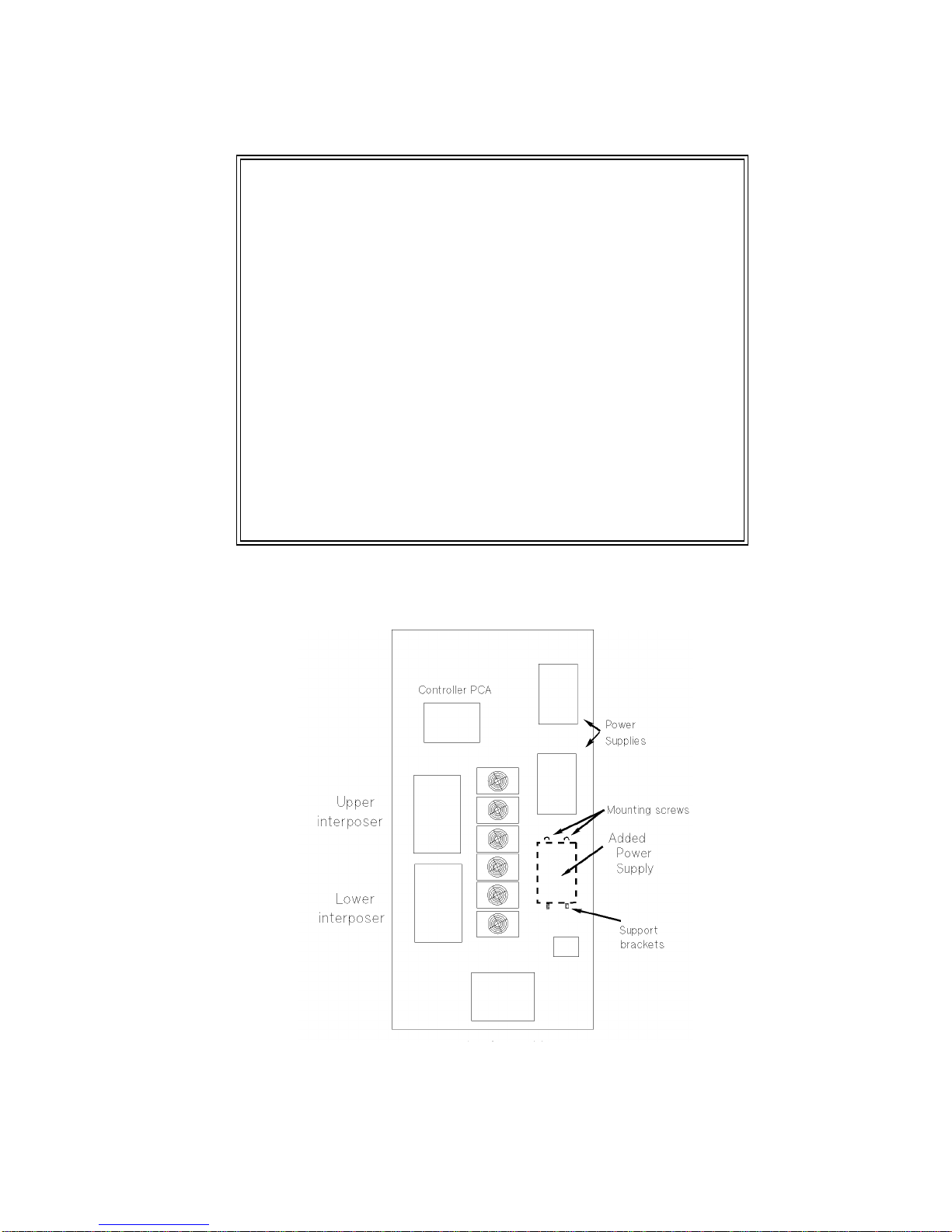
4. Install the additional power supply on the right side as seen in Figure 5.
Figure 5: Power supply location
The magazine guide above is shown as it is oriented when
placing it into the inside right of each stack (as you face the
stacks).
Place the leading tabs (top right in the picture) into the slots
farthest in, then rotate the magazine guide into the stack,
catching the trailing tabs (lower left arrows in picture). Push
the guide against the stack and forward until you (hear/feel)
the latch click into the wall of the stack (the latch is the
"angle"shown in the lower left of the picture).
If this latch does not catch (click into place), the guide is
not correctly mounted and could come out during use.
When installing the magazines in the left stack (as you face
the interior of the jukebox during this step) you will have to
slip the magazines under a small groove running along the
length of the stack.
10
a. Place the power supply on the power supply bracket. Make sure all cables are out of the
way.
b. Mount the new power supply with 2 T-20 screws through mount tabs on the top of the
power supply.
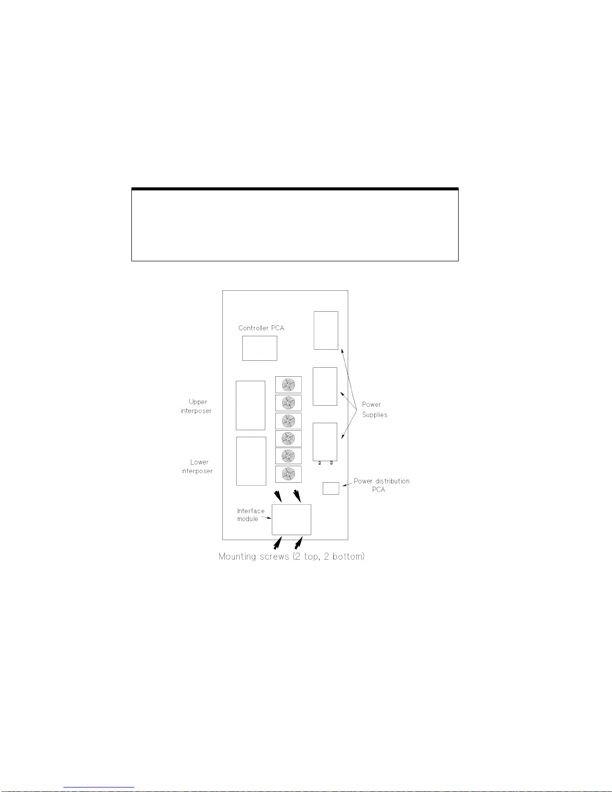
5. Install the new SCSI interface module.
Figure 6: Location of the interface module and mounting screws
a. Remove the current interface module.
1. Disconnect the cables from the module.
2. Remove the 4 T-20 mounting screws and rotate the module down.
3. Remove all cables from the interface PCA.
a. Remove the SCSI interface PCA from the module by removing the 6 T-15 mounting screws.
Note
The new interface module you will assemble has 2 SCSI
interface PCAs to support future upgrades to the number of
drives (upgrading to 8, 10, or 12 drives).
This manual suits for next models
3
Table of contents
Other HP Jukebox manuals

HP
HP Surestore 80ex - Optical Jukebox User manual

HP
HP SureStore 220mx User manual

HP
HP Surestore 160ex - Optical Jukebox User manual

HP
HP StorageWorks 1000ux User manual

HP
HP StorageWorks 3800ux User manual

HP
HP SureStore 220mx User manual

HP
HP StorageWorks 700ux User manual

HP
HP Surestore 125ex - Optical Jukebox User manual

HP
HP SureStore 220mx User manual

HP
HP SureStore 220mx Operating instructions


