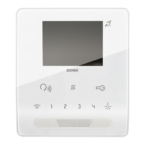
Home Sentinel VI 450 User manual

1
VIDEO
DOORPHONE
SYSTEM
WITH IMAGE MEMORY AND INTERCOM
OWNER’S
MANUAL
INSTALLATION AND OPERATION
BEFORE INSTALLING OR,
OPERATING THE SYSTEM,
PLEASE READ THIS MANUAL
MODEL: VI 450

2
Section Page
Important Safety Instructions………………….........................….......3
Introduction............................…………….............................................4
System Contents........................……………..........................................4
Features......................................................………….............................4
Precautions..........................................................……………................5
Identifying the Parts................................…....……………..............….6
Terminal Inputs and Outputs……………………….………….……..7
Installation.........................................................……………..................8
System Set-up.........................…..............…………….....................9
Operation....................……...........………...............…...............…..9
Expansion Options..............................….........…………….................10.
Identification, Installation & Set-up for MO 451...………..……...11
Identification, Installation & Set-up for CA 456....………..…......13
Installation and Set-up for CA 455....………………………….....14
Door Release Function……………………………………………15
Trouble Shooting Guide.................…..................……………............16
Specifications.................................................……………......…..........17
Warranty......................................................……………......…...........18
Table of Contents

3
Read Instructions – All the safety and operating instructions should be
read before operating this equipment. These instructions should be retained
for future reference
Heed Warnings – All warnings on the equipment and in the operating
instructions should be adhered to. All instructions regarding care and
operation of this equipment should be followed.
Power Sources – Equipment should only be connected to the power supply
specified in the operating instructions or as marked on the equipment.
Power-Cord Protection – Keep cable cords and plugs clear of other
objects, particularly at the point where they exit the equipment.
Cleaning – Clean the equipment by wiping with a soft cloth,
( do not use any abrasive agents or water ).
Non-use Periods – Power cords should be unplugged from the outlet when
left unused for a long period of time.
Object and Liquid Entry – Take care not to drop objects or liquids on any
part of the equipment.
Damage Requiring Service – The unit should be serviced by a qualified
service personnel when:
-The power-supply cord or the plug has been damaged; or
-Objects have fallen, or liquid has been spilled onto the equipment;
or
-The equipment has been exposed to rain; or
-The equipment does not appear to operate normally or exhibits a
marked change in performance; or
-The equipment has been dropped, and/or the enclosure has been
damaged.
Servicing – Do not attempt to service the appliance beyond that described
in the operating instructions. All other servicing should be referred to a
Qualified Distributor’s Service Personnel.
Important Safety Instructions
WARNING: TO REDUCE THE RISK OF FIRE OR ELECTRIC SHOCK, DO
NOT EXPOSE THIS APPLIANCE OR POWER ADAPTER TO WATER OR
MOISTURE

4
Thank you for purchasing the Home Sentinel Video Door phone entry system.
This model allows you to identify and communicate with callers at the door, from
the security and convenience of any room in your home. Visitors activate the
system by pressing a call button on the outdoor camera, which sounds a
doorbell chime as well as turning on the inside video monitor. A 2 way audio
intercom then lets you speak with visitors after first visually identifying them. It
consists of a monitor station and an outdoor camera unit. Expansion is possible
to include up to 8 monitors, 2 outdoor camera stations and 2 dome surveillance
cameras with a simple on-screen menu programming change at the monitor
station.
Utilization of your existing two wire doorbell wiring ensures quick and simple
installation.
For proper usage and application, please read the instruction manual
completely.
• Monitor Station
• Outdoor Camera Station
• AC adapter
• Mounting Hardware (Screw wrench, Sticker, 2 wall
mount screws, 1 Camera door unit assembly screw)
System Contents
• High definition 4" flat screen CRT
• Hand set with 2 way full duplex audio intercom to outdoor
camera stations and monitors
• On screen programming menu for time and day stamp,
memory resolution mode, and extension camera setup
• Auto shut off after 30 seconds for unanswered calls and
90 seconds for answered calls
• High resolution 1/3" B/W CCD image sensor camera
• Wide angle lens with auto iris and auto focus adjustments
• Infrared illumination for clear night vision ( 0 lux)
• Capture/ retain up to 17 call images with date stamp
• The system can be expanded with up to 8 monitor units, up to
2 outdoor camera units plus 2 expansion dome cameras or
1 outdoor camera unit and 3 expansion dome cameras
Introduction
System Contents
Features

5
• Use only the power adapter supplied with the system. The use
of any other power adapter may cause damage to the
system which is not covered under warranty
• Keep it dry. If water should get on it, wipe it off
immediately. Water contains minerals that can corrode
electronic circuits
• Do not use or store in area of high levels of dirt or dust.
The electronic circuit may be contaminated, and any moving parts
will wear prematurely
• Avoid installing the monitor directly into the sun or in any
other intensely bright locations
• Do not install the monitor in areas where it may be exposed
to excessive moisture or extreme temperatures
• Do not install near corrosive chemicals or harmful gases
• Before installing the system completely, it is a good idea to
check for proper operation by temporarily connecting the
monitor to the camera and powering up units.
Precautions

6
V
I 450 Monitor
Description
1. Pin Socket
2. Wiring Terminal
3. DC Power Socket
4. 4“ B/W Flat CRT Screen
5. Power LED
6. Volume Tuner
7. Broadcasting and Intercom Call Button
8. Lock Release Button
9. Audio & Video Monitoring Button
10. Brightness Control
11. Memory Status LED
12. Sharpness Control
13. AC adapter
14. Fasten Screws
1. Pin Socket
Used to connect to basic house unit
2. Wiring Terminals
Terminals used to connect camera units, expansion
monitors, etc
3. DC Power Socket
Used to plug in the AC power adapter
4. High Resolution 4" B/W Flat CRT Screen
To view image delivered from camera(s)
5. Power LED
Indicates that power is on
Identifying the Parts

7
6. Volume Control
Use to adjust chime volume level and voice level
7. Broadcasting & Intercom Call Button
Use to initiate the intercom function (a doorbell chime
will be heard )
8. Lock Release Button
Press to remotely unlock/open your door (requires
electric deadbolt, optional)
9. Audio & Video Monitoring Button
Press to manually activate camera unit for picture and sound
10. Brightness Control
Rotate to adjust picture brightness of image
11. Memory Status LED
To indicate memory status
12. Sharpness Control
Rotate to adjust sharpness of image
13. AC adapter
14. Fasten Screws: Used to mount the wall plate
VI 450 Monitor ( Terminal Inputs and Outputs )
COM
OUT -
OUT +
CAM3
CAM3
CAM2
CAM2
DR2 /
CAM1
DR1
Connect to the IN - and IN + terminal
of the MO 451 Expansion monitor
Connect to Dome Camera CA456
Connect to Dome Camera CA456
Connect to second door camera
CA455 or Dome Camera CA 456
Connect to Door Camera CA 455
Identifying the Parts

8
CA 455 CA 456 CA 456 CA 456
MO451
Door Release Monitor
+ -
Please note: Turn off the power to all units being used before connecting
or disconnecting cables
1. Choose a suitable location, then fasten the wall mount plate
to the monitor unit using the two wall mounting
screws provided.
2. Connect the outdoor camera and monitor using the
standard doorbell wires. Connect 2 wires from the DR1
terminal on the monitor to the Monitor terminals on the back of
the outdoor camera unit.
3. To mount the outdoor camera unit, fasten wall mount
case using assembly screw. If door release mechanism is
used connect two wires from the back of the camera
marked Door Release + / - terminals
4. Connect AC power
5. Press Audio & Video Monitoring Button to test unit
6. Adjust the view angle of the Camera unit. Use the screw
wrench provided to poke through the two holes at the back
of the unit.
7. Assemble camera unit to wall mount case with
camera assemble screw and put sticker on to cover screw
Installation

9
1. To enter set-up mode for on-screen programming press and
hold the left button( Broadcasting and Intercom Button ) for
2 seconds when the handset is “ on the hook “ . You will hear
a chime before entering Set-up mode.
2. Press the left and right button on the monitor to select the item,
and the middle button to alter or make a change to the menu,
such as the time, date, Gray level settings, cameras that
are Active or off. A fast flash of the memory status LED
reminds you to adjust the clock. The back-up battery to the
clock lasts 4 hours when there is a power failure.
Note:Gray Level indicates Memory image quality
LO (17) for Lower resolution 17 Picture image capacity
HI (13) for higher resolution 13 Picture image capacity
3. Reset handset to End Setup Mode
1. Visitor Calls From Camera Unit
• After 4 seconds of the call, the system will grasp the
picture memory automatically
• After the call, if the handset remains on the hook the
system will cutoff after 30 seconds
• If the handset is picked up, you have 90 seconds
to communicate before it automatically cuts off or hang-up
to terminate a call
• If the memory status LED flashes slowly it means the
images are captured in the memory
2. Audio & Video Monitoring
• Press the right button for monitoring a camera
• Press button again to switch monitoring channel ( If there
is more than one camera connected)
• Reset the handset to end the monitoring mode
System Set-Up
Operation

10
3. Inspect New Memory
• Slow flash on the memory status LED indicates memory
is captured
• Press and hold the middle button for 2 seconds, you will hear
a chime before entering the Inspection mode
• Press left & right button to scroll pictures
• Reset Handset or when visitor calls this will end the
Inspection mode
4. Others
• Fast flash of memory LED reminds you to adjust the clock
• If you wish to retain the memorized image, please
disconnect the AC power or disconnect the monitor unit
from the wall mount plate. Re-install the monitor unit
for reviewing the memorized image.
MO 451 : Expansion of MO 451( no memory function )
Can enable Broadcasting & Intercom Function
CA 456 : Expansion of Dome Camera for Audio & Video Monitoring
CA 455 : Expansion of a second door camera unit
Expansion Options
Operation
Table of contents
Other Home Sentinel Intercom System manuals