Hobby Components V2 4x4x4 LED Cube Kit User manual

Hobby Components
V2 4x4x4 LED Cube Kit
Build Guide
Document version 1.0

PLEASE NOTE
This build guide is for version 2 cube kits only. If you have an older version kit (V1 or V1.1)
you can find the correct build guide on our blog site here:
https://blog.hobbycomponents.com/?p=412
To make this kit as easy to build as possible we have designed it to only use through-hole
components. However, some familiarity with soldering is required to construct this kit .
DISCLAIMER
This document is provided "as is". Hobby Components Ltd makes no warranties, whether
express, implied or statutory, including, but not limited to, implied warranties of
merchantability and fitness for a particular purpose, accuracy or lack of negligence. Hobby
Components Ltd shall not, in any circumstances, be liable for any damages, including, but
not limited to, special, incidental or consequential damages for any reason whatsoever.
COPYRIGHT NOTICE
This document, including content and artwork is copyright of Hobby Components Ltd and
may not be reproduced without written permission. If you paid for or received a copy of this
manual from a source other than Hobby Components Ltd, please contact us at

Before You Start
Kit contents
The first thing you need to do is check that all the components are enclosed in your kit. Here is a
check list of all the components included in the kit:
QTY
Description
1
Version 2 4x4x4 Cube Kit PCB
16
180 Ohm resistors (BRN, GRY, BLK, BLK, BRN)
2
220 Ohm resistors (RED, RED, BLK, BLK, BRN)
1
10K Ohm resistor (BRN, BLK, BLK, RED, BRN)
3
100nF ceramic capacitor (marked 104)
1
470nF ceramic capacitor (marked 474)
1
SR1100 Diode
1
28 pin IC socket
1
18 pin IC socket
1
ULN2003 18 pin IC
1
ATMega328 28 pin IC
1
Push button
1
2.1mm DC socket
1
5 Pin right-angled header (may be supplied as a 40 pin breakable strip)
20 + spares
Male to female sockets (supplied as a 40 pin breakable strip)
4
5mm white LEDs
64 + spares
3mm LEDs
25cm
Solid core wire
1
USB to 2.1mm DC cable

Required tools
In order to build the cube, you will need the following tools:
1. Soldering Iron (Ideally with a fine tip)
2. Solder
3. A small pair of snips or side cutters
4. A pair of small, long nose pliers
Recommended
4x4x4 V2 Cube kit LED template (SKU: HCPROT0101)
OR:
A piece of perspex / plywood which will be used as a jig for soldering the LEDs that
make up the cube
3mm drill bit and drill
Part 1: Building the PCB
Soldering notes
Take the PCB out of your kit and you’ll notice that one side of the PCB has white silkscreen
printed on it with the other side being completely blank. All components, apart from the male
to female sockets, will be soldered to the silkscreen side of the PCB.
Soldering tips:
When soldering components to a circuit board it is always best to start with the smallest
components first. This helps keep the board flat and stops access to pads from being
restricted by larger components. We have deliberately ordered the steps within the guide so
that components are soldered in order of height.
The first step is to start by soldering the resistors. In your kit these will be marked
appropriately. The orientation of most of the components doesn’t matter but we will point out
any components where the orientation does matter. In these cases it is important to make
sure you have them inserted correctly.
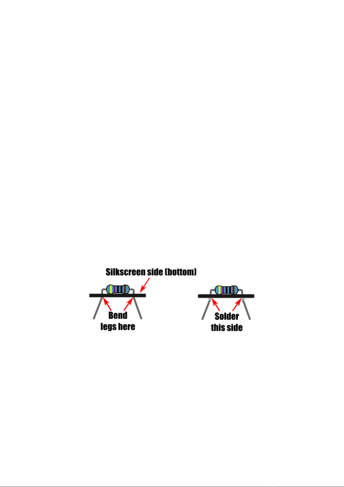
Unless otherwise stated, solder components to the PCB by inserting their legs through the
appropriate pad holes on the silkscreen side of the PCB, then flip the PCB and solder the
component legs to the PCB pads on the opposite side (non-silkscreen side).
For components with flexible legs like resistors and capacitors you can keep them held in
place by splaying the legs outwards slightly. Once soldered any excess leg can be trimmed
using a pair of snips or side cutters.

When soldering components with multiple pins it is recommended to solder one pin first,
then check that the component is still sitting flat to the PCB, then solder the rest of the pins.
In the case of IC sockets, solder pins in opposite corners of the socket first. That way if the
socket isn’t sitting flat it is then easy to reheat the soldered pads to flatten the socket before
soldering the rest of the pins.
With these tips in mind we can now start soldering the components to the PCB. Solder each
type of component in the following sequence…
Step 1: Resistors
16x 180 Ohm resistors R2 to R17
(marked BROWN , GREY , BLACK,
BLACK, BROWN )
The orientation of the components doesn’t
matter.
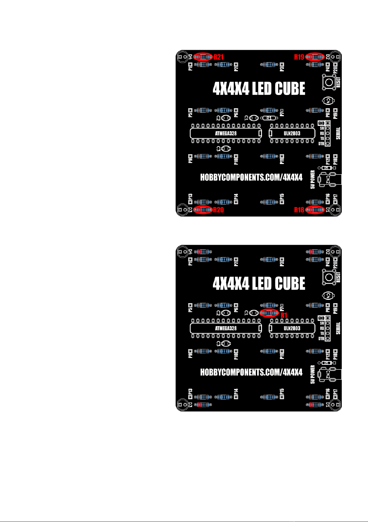
4x 220 Ohm resistors R19 to R21
(marked RED , RED , BLACK, BLACK,
BROWN )
The orientation of the components doesn’t
matter.
1x 10K Ohm resistor R1 (marked
BROWN , BLACK , BLACK, RED ,
BROWN )
The orientation of this component doesn’t
matter.

Step 2: Diode
1x SR1100 Diode D5
Note that the orientation of the diode is
important - solder it to the PCB with the
silver band pointing to the edge of the PCB.
Step 3: IC sockets
1x 18 pin & 1x 28 pin IC socket
In both cases solder the sockets with the
notch end of the socket pointing into the
PCB. Be careful when inserting the sockets
that none of the pins bend under the socket
instead of going through its pad hole - they
should drop into holes without any
resistance.

Step 3: Serial port
1x 5 pin right-angled header
This may be supplied as a 40 way strip
which can be broken into a 5 pin section.
Solder this header with the pins pointing to
the outside of the PCB.
Step 4: Capacitors
3x 100nF ceramic capacitors C1, C2, &
C3 (marked 104)
1x 470nF ceramic capacitor C4
(marked 474)
The orientation of the components doesn’t
matter.

Step 5: Switch
1x Push button switch
Note that the orientation of the switch is
important - referencing the image, insert
the switch into the PCB so that the pins are
on the top and bottom sides of the switch.
Step 6: 5V Power socket
1x DC Socket
Table of contents
Popular Lighting Equipment manuals by other brands


Qazqa
Qazqa Suplux SL 3 Black 103062 instruction manual

Commercial Electric
Commercial Electric 54568141 Use and care guide

CREE LIGHTING
CREE LIGHTING 304 Series installation instructions

Goobay
Goobay 49867 user manual

ECOMAN ITALIA
ECOMAN ITALIA LED T8 instruction manual

Alkalite
Alkalite Krypton KT-81 user manual


