
HME System 400 User manual

HME#
400472
Rev – 03/15/02
System 400
Wireless Audio System
Operating Instructions
(For Full-Duplex and Half-Duplex Operations)

Table of Contents
I. GENERAL ..................................................... 1
II. EQUIPMENT FUNCTIONS AND USE ................................ 1
A. Base Station ................................................ 1
B. COM400CC COMMUNICATOR ................................ 2
®
1. Controls and Connector ................................... 2
2. Wearing the COM400CC COMMUNICATOR ................... 3
®
3. Charging the COM400CC Batteries .......................... 4
C. COM400BP COMMUNICATOR ................................. 7
®
1. Controls and Connector ................................... 7
2. Wearing the COM400BP COMMUNICATOR ................... 8
®
3. Charging the COM400BP Batteries ........................... 9
D. COM430BP COMMUNICATOR ................................ 12
®
1. Communicator Controls ................................... 12
2. Wearing the COM430BP COMMUNICATOR .................. 13
®
3. Charging the COM430BP Batteries .......................... 14
III. SYSTEM 400 OPERATION ....................................... 18
A. COMMUNICATOR Operation ................................. 18
®
B. Speed-Team Drive-Thru Operation ............................. 19
C. Remote Display Operation .................................... 19
D. Message Repeater Operation and Setup ......................... 19
IV. HOW TO CARE FOR THE EQUIPMENT ............................. 20
A. The COMMUNICATOR ...................................... 20
®
1. Proper Handling of Headset Cables and Connectors ............ 20
2. Cleaning the Equipment ................................... 20
B. The Battery Charger ......................................... 20
V. IN CASE OF PROBLEMS ........................................ 21
VI. SPECIFICATIONS .............................................. 24
VII. ACCESSORIES AND OPTIONAL EQUIPMENT ........................ 27
VIII. FCC NOTICE .................................................. 27
The HME logo and the word COMMUNICATOR are registered trademarks of HM Electronics, Inc.
®
© Copyright HM Electronics, Inc. — March 2002

List of Figures
Figure Title Page
1 System 400 Base Station ........................................ 1
2 COM400CC COMMUNICATOR .................................. 2
®
3 COM400CC control buttons ..................................... 2
4 Cable connectors showing matching pin positions ................... 2
5 Correct wearing of the COM400CC ............................... 3
6 Remove and replace Communicator batteries ....................... 4
7 Inserting a battery into the AC900 Battery Charger ................... 4
8 Battery charging indicator lights .................................. 5
9 Battery going into AC900 storage port ............................. 5
10 COM400CC battery charging in the AC910 Battery Charger ............ 6
11 COM400BP COMMUNICATOR .................................. 7
®
12 COM400BP controls, connector and indicator light ................... 7
13 Plug the headset-cable connector into the cable receptacle ............ 8
14 Insert belt through belt loop on back of Communicator pouch ........... 8
15 Correct wearing of Communicator headset .......................... 8
16 Installing the battery ............................................ 9
17 Opening the battery compartment ................................. 9
18 AC420 Battery Charger shown with a properly installed battery ......... 10
19 COM400BP battery charging in the AC910 Battery Charger ........... 11
20 COM430BP COMMUNICATOR ................................. 12
®
21 Communicator controls ........................................ 12
22 Communicator transceiver in pouch .............................. 13
23 Correct wearing of the COM430BP ............................... 13
24 Installing the COM430BP battery ................................. 14
25 Opening the COM430BP battery compartment ...................... 14
26 HS30 Headset ............................................... 15
27 HS30 Headset transceiver ..................................... 15
28 AC30 Battery Charger ......................................... 16
29 AC930 Battery Charger ........................................ 17
30 Base station circuit boards ...................................... 23

1
Figure 1. System 400 Base Station
I. GENERAL
The System 400 is a wireless audio system primarily for use at quick-service restaurants.
II. EQUIPMENT FUNCTIONS AND USE
A. Base Station
Front –
System indicator lights
!! POWER light is on when the base station has power.
!! MESSAGE RECORD light is on RED when the base station is ready to record
message #1 for the message repeater, and blinking RED while message #1 is
being recorded. It is on GREEN when the base station is ready to record
message #2 for the message repeater, and blinking GREEN while message #2
is being recorded. The MESSAGE REPEATER button must be IN.
!! RECEIVE light is used only for troubleshooting, but is also on during channel-A
and channel-B transmissions.
!! “A” light is on during channel-A transmission.
!! “B” light is on during channel-B transmission.
!! VEHICLE light is on when a vehicle is present in the drive-thru lane or when
the system is in vehicle-detect override.
Bottom –
!! PUSH FOR RECORD MODE button; must be pushed IN and released once to
prepare the base station to record message #1 for the message repeater, or
pushed IN and released twice to record message #2.
!! MESSAGE REPEATER button; must be IN to use the message repeater, OUT
when the message repeater is not being used.
!! SPEED TEAM button; must be IN for speed-team operation, OUT for normal
drive-thru operation
!! VEHICLE DETECTOR button; to override a vehicle detector, push and leave
IN: to reset vehicle detector, push IN and leave In for 5 seconds, then push
again and leave OUT for normal vehicle detection.
Left Side –
!! WIRED/WIRELESS button; must be OUT when using the wireless
System 400, IN when using a wired backup system.

2
Figure 2. COM400CC COMMUNICATOR®
Figure 3. COM400CC control buttons.
Figure 4. Cable connectors showing matching pin positions
B. COM400CC COMMUNICATOR
®
The COM400CC COMMUNICATOR®
consists of a transceiver unit and a
lightweight headset designed to be used
with the HME Wireless Drive-Thru Audio
System 400. The transceiver is worn
around the collar, and the headset plugs
into a connector on the transceiver unit.
1. Controls and Connector
Plug the headset cable connector into the cable connector on the COM400CC
collar unit, as shown in Figure 4. Be careful to correctly match the positions of the
pins inside the connector.

3
Figure 5. Correct wearing of the COM400CC
2. Wearing the COM400CC COMMUNICATOR
®
!Place the Communicator collar unit around your neck and put the headset on your
head as shown in Figure 5.
!Adjust the headset band so it rests securely on top of your head, with the
microphone to the side of your mouth.
!Adjust the Communicator so it fits comfortably around your collar.
!Fasten the clothing clips to your collar as shown in Figure 5.

4
Figure 6. Remove and replace Communicator battery
Figure 7. Inserting a battery into
the AC900 Battery Charger
3. Charging the COM400CC Batteries
When there are good batteries in the COMMUNICATOR and the power is on, the red
®
light above the power (PWR) button will be lit. This light only indicates the power is on.
It does not indicate how much power is left in the batteries. As the batteries weaken
during routine use, you will hear a repeating beep in the earpiece, indicating the
batteries need to be replaced. When this happens, remove the battery from the
Communicator as shown in Figure 6. Place both batteries in the AC900 Battery
Charger for recharging. Refer to Figures 7 through 9. Replace the batteries in the
Communicator with fresh, fully charged batteries. Typical battery life with normal use is
8 to 10 hours.
CAUTION: To prevent damage, turn Communicator OFF before removing or
installing batteries.
Installing and Removing Communicator Batteries:
Charging COM400CC Batteries in the AC900 Battery Charger:
Place up to four COM400CC batteries in the charger for charging at a time. See Figure 7.
The red Charging light, adjacent to a battery being charged will go on and remain on
while the battery is charging. Routine battery charging takes up to 3 hours.
NOTE: The COM400CC uses “smart batteries.” That means each battery maintains a history of the
number of times it has been charged. The
AC900 Battery Charger reads and updates
this history each time a battery is charged.
This information is used to automa-tically
initiate conditioning cycles, which improve the
battery’s performance and prolong its life. A
conditioning cycle consists of a complete
discharge before a battery is charged. This
happens each time the battery history
indicates it has been charged 10 times since
the last conditioning cycle. While a battery is
discharging, the red Charging light next to it
will blink on and off at 2-second intervals.
The conditioning cycle takes up to 6 hours.

5
Figure 8.
Battery charging indicator lights
Figure 9.
Battery going into AC900 storage port
When a battery is fully charged and ready for
use, its red “Charging” light will go off and the
green “Ready” light next to it will go on.
CAUTION: Do not remove batteries from the charger until the green READY light
is lit, or the charger will reset and the charge cycle will begin again.
To remove a fully charged battery from the
battery charger, push the battery from the end
near the status lights.
Store fully charged batteries in the storage ports
on the right side of charger until you need them,
as shown in Figure 9.
CHARGING LIGHT STATUS TABLE – WITH BATTERY INSERTED
CHARGING LIGHT WHAT IT MEANS WHAT TO DO
Red blinks: Either the battery or the charger has
2 times quick - 3 seconds off a problem. Mark the battery and
Discharge error
retry in a different charging port.
The battery is faulty if it has the
same problem in a different port
AND a known-good battery passes
in the same ports. The charger
circuitry is faulty if a known-good
BATTERY fails in the same ports.
Red blinks:
3 times quick - 3 seconds off Charging error
Red blinks:
4 times quick - 2 seconds off Low-battery error
Red blinks:
5 times quick - 2 seconds off Charging error
Green blinks:
2 second on - 2 second off Read-write error
Green blinks:
3 times quick - 3 seconds on Memory full
Red and Green blink alternately Authentication error

6
Figure 10.
COM400CC battery charging in the AC910 Battery Charger
Charging COM400CC batteries in the AC910 Battery Charger:
Place up to four COM400CC batteries in the charger for charging at a time. The red Charging
light, adjacent to a battery being charged will blink for a few seconds when the battery is placed
in the charger, then will go on and remain on while the battery is charging.
NOTE: The COM400CC uses “smart batteries.” That means each battery will retain charging
information that will cause it to automatically discharge completely before being recharged,
every tenth time it is placed in the charger. This will improve the battery’s performance and
life. While a battery is discharging, its red Charging light will blink on and off at 2 second
intervals.
When the battery is fully charged and ready for use, the red light will go off and the green
Ready light adjacent to the battery will go on.
To remove fully charged batteries from the battery charger, push the battery from the end
near the status lights. Store fully charged batteries in the storage ports until you need them.
7
Figure 11. COM400BP COMMUNICATOR®
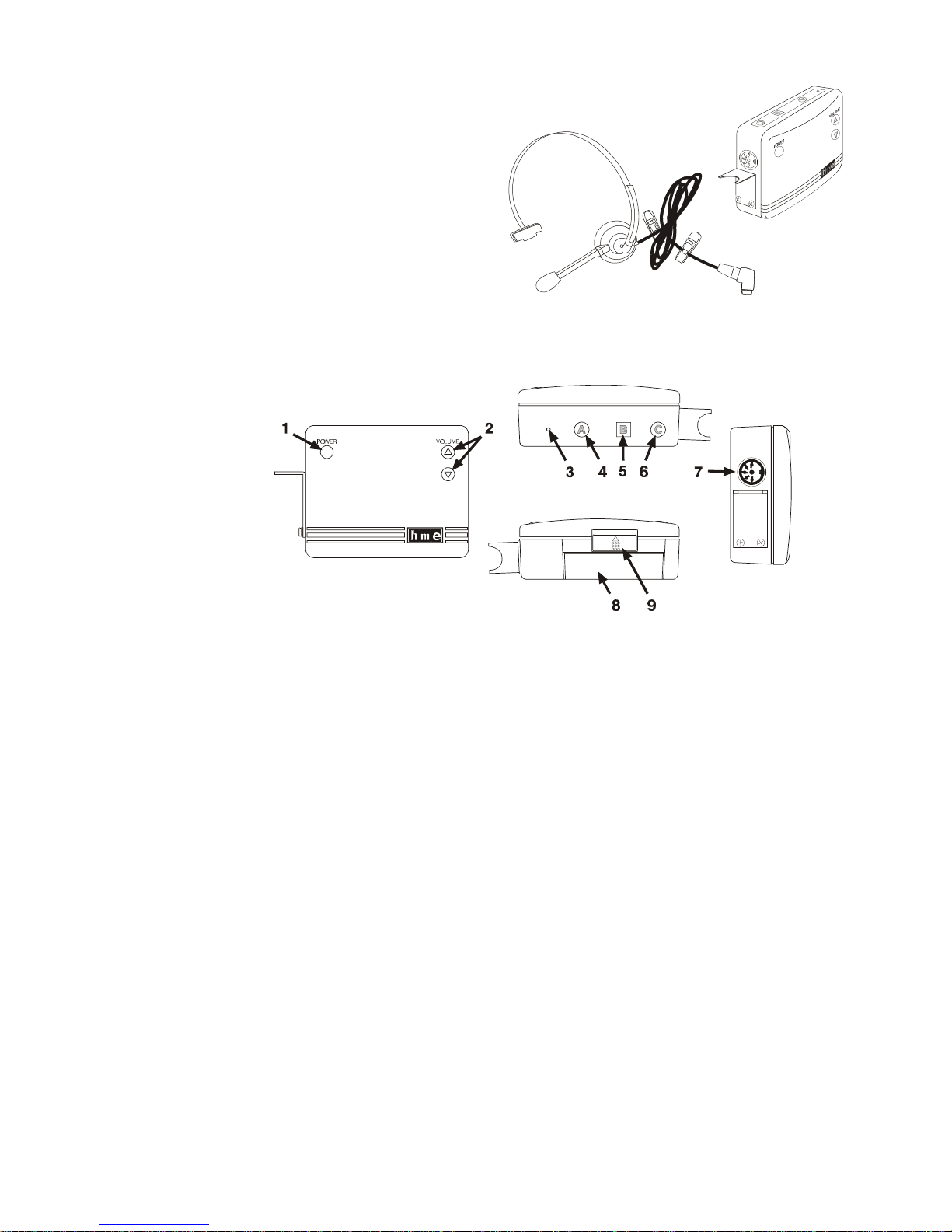
Figure 12. COM400BP controls, connector and indicator light
C. COM400BP COMMUNICATOR
®
The COM400BP COMMUNICATOR®
consists of a belt-pac transceiver unit and
a lightweight headset designed to be
used with the HME Wireless Drive-Thru
Audio System 400. The Communicator is
worn around the user's waist, and the
headset plugs into a connector on the
transceiver unit.
1. Controls and Connector
1– POWER button: turns Communicator on and off.
2– VOLUME buttons: adjust listening level in earpiece.
3– Power-on light: lights when power goes on, and remains lit until battery needs
replacing or Communicator is turned off. The power-on light blinks when
transmitting on “A” or “B” channel.
4– Button A: allows two-way communication when pushed and held; when it is
released, the user can listen only.
5– Button B: must be pushed and held to talk, and released to listen.
6– Button C: used to change lanes in dual-lane operations.
7– 5-pin DIN receptacle: receptacle for earpiece/microphone cable connector.
8 – Battery: provides power for the transceiver unit.
9 – Battery release latch: slides to release battery for removal, and snaps in place
when a battery is inserted to secure battery in Communicator.
Table of contents
Other HME Microphone System manuals


Popular Microphone System manuals by other brands


Sennheiser
Sennheiser Evolution Wireless Digital EW-DX EM 2 quick guide

Alpha Technologies
Alpha Technologies RBMS Installation & operation manual

SWIT Electronics Co.,LTD.
SWIT Electronics Co.,LTD. CW-S150 user manual

Shure
Shure UA844 user guide

Panasonic
Panasonic SHFX70 - DVD HOME THEATER WIRELESS SYSTEM operating instructions

Pyle
Pyle PDWM5000 user manual