HISEER GSWW60 Instruction manual

GEOTHERMAL HEAT PUMP
Installation ,Operation &Maintenance Manual
The Installation of this unit is to adhere to all Local
Building Codes and Standards

1
Pre-Installation
Important Site Instructions
The installation, commissioning, inspection, maintenance and repairs must only be carried out by
a ualified person.
All electrical wiring must be completed by a licensed electrical contractor in accordance with the
appropriate standards.
The drilling work re uires a permit from your local council.
The heating system and heat source must be properly designed and dimensioned to ensure an
efficient operation. It is particularly important to keep water flow temperatures as low as possible.
The minimum heating water flow rate through the heat pump must be assured in all operating
states of the heating system.
Movement and storage
The unit must not be transported, moved or stored at greater than a 30° angle from the upright
position. Install and store the unit in a dry area. They are not rated for outdoor use.
Safety
If a refrigerant leak occurs, remove the complete charge using a recovery unit and store the
refrigerant in mobile container.
Note: care is to be taken as the refrigerant can breakdown due to high temperature, these
refrigerants by-products are dangerous.
Once the leak has been repaired recharge the unit with the correct filling weight and the type
found on the unit’s nameplate.
Note: ensure the correct refrigerant gas is used to recharge the unit as an incorrect gas can cause
damage beyond repair to the compressor.
Do not use oxygen to purge lines or to pressurize a unit for any purpose.
Oxygen gas reacts violently with oil, grease and other common substances.
Use only refrigerant or dry nitrogen for testing.
Never exceed the specified maximum operating pressures.
Do not un-weld or flame cut the refrigerant lines including any refrigerant circuit components
until the entire refrigerant (li uid and vapour) has been removed from unit. Traces of vapour
should be displaced with dry nitrogen.
Refrigerant in contact with an open flame will produces toxic gases.
Ensure that the necessary safety protection e uipment is available when servicing. Have the
appropriate fire extinguishers for that system.
Do not siphon refrigerant.
Avoid spilling li uid refrigerant onto the skin or splashing it into the eyes. Use safety goggles.
Wash any spills from the skin with soap and water. If li uid refrigerant enters the eyes,
immediately and abundantly flush the eyes with water and consult medical advice.
Note: Never apply an open flame or live stream to a refrigerant container. This can dangerously
overpressure and cause an explosion.
Pre-Installation

2
Installation Location and Positioning
The unit must be installed in a protected area that is free from rain and water penetration.
The unit must be installed on a solid level surface, preferably on a concrete pad not connected to
the main house slab foundation.
Allowances for good ventilation around the installation must be provided.
In normal operations to prevent condensation collecting on cold pipes the thermal insulation of
any cold components should be to a high level.
The unit will produce noise that is above the minimum 45 decibel rating. Therefore the unit should
be located so that it is well away from bedrooms, offices, living areas or noise sensitive areas
including neighbour’s bedrooms.
There must be suitable distances between the unit and the building to ensure normal operation and
enough room for maintenance re uirements.
Installation Location and Positioning

3
Buffer Tank
A buffer tank is recommended to ensure a trouble free heat pump operation. A suitable buffer tank
can avoid excessive heat pump cycling (switching on and off).
The buffer tank provides a hydraulic separation from the volume flow in the heat pump and
heating circuits. The volume flow in the heat pump circuit remains constant, even if the heating
circuit volume flow is reduced by thermostatic valves.
If the total of the systems water volume is less than 12L/KW then a buffer tank should be added to
reduce the compressor from ON/OFF cycling. This will prolong the compressor life span.
When a buffer tank is installed, the heating system will absorb energy from the buffer tank first.
To save energy consumption ,install the indoor pump P1 that is switched on only when compressor
is on. This is by changing EV01 to “1”.
RT sensor should be taken out of the unit and put into buffer tank’s sensor pocket. The RT sensor
is located at lower submerged sensor pocket of the plate heat exchanger. The RT sensor in the
buffer tank will control the tank temperature by starting and stopping the compressor and pump
together as re uired.
If RT sensor has not been changed to buffer tank’s sensor pocket when EV01 has been change to
“1”, when the unit reaches its set temperature ,the compressor will stop, pump P1 will also stop
accordingly due to EV01 being set to “1”. When this occurs ,there is no water circulation between
the heat pump and buffer tank. RT will keep its stopped temperature ,not the buffer tank water
temperature. RT then can not switch on compressor and pump P1 even when buffer tank water is
getting cold. Changing the RT sensor into the buffer tank will avoid this problem.
Buffer Tank
4
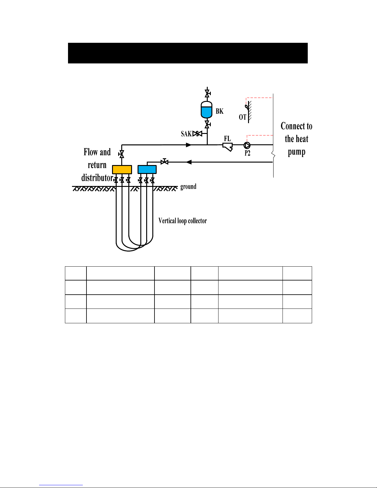
System Overview Vertical Ground Loop System
Name
Description Location
Name Description
Location
P2 Outdoor side water
pump External OT Outdoor temperature
sensor Internal
SAK
Safety valve External FL Particle filter External
BK Brine tank/expansion
tank External
Systems Overview Outdoor side)

5
System Overview Horizontal Ground Loop System
Name
Description Location
Name Description
Location
P2 Outdoor side water
pump External OT Outdoor temperature
sensor Internal
SAK
Safety valve External FL Particle filter External
BK Brine tank/expansion
tank External
Systems Overview Outdoor side)

6
System Overview Ground Water with Intermediate Heat Exchanger
System
Name
Description Location
Name Description Location
P2 Outdoor side water pump
External OT Outdoor temperature
sensor Internal
P3 Ground water pump External FL Particle filter External
BK Brine tank/expansion
tank External SAK Safety valve External
FW Water flow switch External FI filter External
DP Intermediate heat
exchanger External
Principle of Operation:
An intermediate heat exchanger (DP) should be installed to prevent ground water damaging or
contaminating the unit’s internal heat exchanger. A plate heat exchanger that is able to be cleaned
is recommended for this situation that can be disassembled for cleaning and repair or any damage
plates can be replaced. Anti-freezing measurement must be adopted to protect the ground water
circuit.
Systems Overview Outdoor side)
7
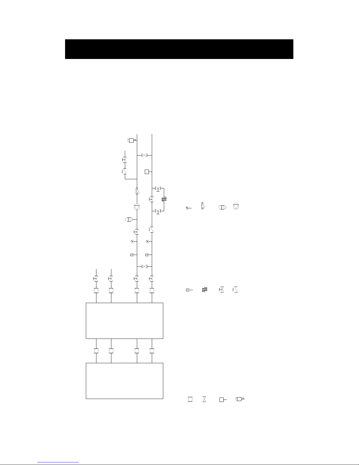
Several units could be connected together to build a large system.
Each controller is set to different cooling, heating set point (2-3 degree difference)so they will not
start at the same time to reduce start current.
All units water pump control signal connected together to A/C contactor which supply power for
water pump so the water pump can run as long as any unit is running.
GSWW60 GSWW60
Connect outdoor
system
Connect
indoor system
soft-joint for reducing vibration
between machine and system
by-pass valve
water pressure gauge
filter
automatic air vent valve
temp gauge
electronic heater
shut off valve
non-returning valve
expansion tank
water pump
water flow switch ( If it is assembled
inside the factory, no need to install)
Systems Overview Indoor side)

8
Heating working principle:
To set two units in parallel operation, set the primary unit to the re uired parameters, unit two is to
have 3~5°C difference of ST01,ST02 and ST05 to allow for energy stage control.
Switch on both units’ A/C switches one by one, if the RT parameter is lower than the set values of
both units, then the units will start to heat together. The unit with the lower ST02+ST04 value will
stop first, the other will stop as well when the RT rises above its set value. Then both units will
stop.
The unit with the higher ST02-ST04 value will start first again to heat when the buffer tank’s RT
drops. If this unit can meet the heating capacity then the RT will not drop any further, only this
unit will run as re uired. If the heating load is bigger than the capacity of one unit then the RT will
continue to drop to below the second unit ST02-ST04 value, the second unit will start increasing
the heating capacity.
Systems Overview Indoor side)

9
Installation
Installation must be carried out in accordance with current Standards and Building Codes
.
The
heat pump does not come fitted with shutoff valves and these must be fitted outside of the heat
pump to facilitate future service
.
Important
The pipe work must be flushed before the heat pump is connected so that any contaminant does
not damage the unit’s internal component parts
.
Gro nd Loops:
When dimensioning the ground collectors, consideration must be given to the geothermal location,
type of rock, soil structure and the size of the heat pump
.
When installing the collector pipe ensure it rises constantly towards the heat pump to avoid air
pockets. If this is not possible install high points to vent the air. The ground collectors must be free
of all air.
All brine pipes that enter any rooms must be insulated against condensation. The expansion tank
(BK) must be installed as the highest point in the collector system and on the incoming pipe before
the brine pump.
Note: Condensation may drip from the expansion tank. Position the expansion tank so that it isn’t
in the way of other e uipment
.
When installing the circulation pump for the brine circuit, position the electric connection at the
12 o’clock position to prevent ingress of condensate.
Ensure ade uate thermal and sound insulation of all pipes routed through wall apertures.
Thermally insulate pipes on the inside buildings and installed with a vapour seal. As the
temperature of the ground collector system can fall below 0°C, the fluid must be protected against
freezing down to –15°C. The details of the types of antifreeze used are to be left near the unit for
future servicing.
Shut-off valves should be installed as close to the heat pump as possible
.
In the case of a connection to an open ground water system, an intermediate frost-protected circuit
must be provided, due to the risk of dirt and freezing that could occur in the evaporator, this
re uires an extra exchanger.
IMPORTANT:
The recommended ground loop pipe length must be adjusted according to the local conditions.
The length of the collector pipe varies depending on the rock/soil conditions and on the heating
system, i.e. radiators or floor heating. Max length per collector should not exceed 200m.
Installation
Table of contents
Other HISEER Heat Pump manuals


Popular Heat Pump manuals by other brands


Mitsubishi Electric
Mitsubishi Electric PUZ-SWM60VAA Service manual

Dimplex
Dimplex LI 16I-TUR Installation and operating instruction

Carrier
Carrier WSHP Open v3 Integration guide

TGM
TGM CTV14CN018A Technical manual

Carrier
Carrier 38MGQ Series installation instructions

Kokido
Kokido K2O K880BX/EU Owner's manual & installation guide

Viessmann
Viessmann VITOCAL 300-G PRO Type BW 2150 Installation and service instructions

Carrier
Carrier 48EZN installation instructions

Viessmann
Viessmann KWT Vitocal 350-G Pro Series Installation and service instructions for contractors

Ariston
Ariston NIMBUS user manual

Weishaupt
Weishaupt WWP L 7 Installation and operating instruction

GE
GE Zoneline AZ85H09EAC datasheet