Hirschmann OZD FIP G3 Manual

Description and Operating Instructions
Fiber-Optic FIP Repeater OZD FIP G3
Port 1
System
Port 1
Port 2
Port 3
OZD FIP G3

Order numbers:
OZD FIP G3 933 847-421
Description and Operating Instructions 933 847-901
Fiber-Optic FIP Repeater OZD FIP G3
Description and Operating Instructions are protected by copyright.
All rights reserved. The reproduction, duplication, translation,
conversion to any electronic medium or machine-readable form
in whole or in part is not permitted
The following Description and Operating Instructions have been
produced by Richard Hirschmann GmbH & Co. to the best of the
company's knowledge. Hirschmann reserves the right to amend the
contents of this description and operating instructions without prior
notice. Hirschmann cannot provide any warranty or guarantee with
regard to the correctness or accuracy of the information contained
in this Description and Operating Instructions.
Under no circumstances can Hirschmann be held liable for any
damage arising from the use of the fiber-optic FIP repeater OZD
FIP G3.
© 1998 Richard Hirschmann GmbH & Co
The naming of registered trademarks in the following description
and operating instructions, even if not specifically identified as such,
should not warrant the assumption that such names are not subject
to the terms stipulated in the trademark and trademark protection
legislation and that they can therefore be freely used by anyone.

3
Version 1.0 11/97
Contents
1 Introduction . . . . . . . . . . . . . . . . . . . . . . . . . . . . . . . . . . . . . . . . . . . . . . . . . . . . . . . . . . . . . 25
2 Network Topologies . . . . . . . . . . . . . . . . . . . . . . . . . . . . . . . . . . . . . . . . . . . . . . . . . . . . . . 27
2.1 Redundant optical ring (two-fiber ring) . . . . . . . . . . . . . . . . . . . . . . . . . . . . . . . . . . . . . 27
2.2 Line topology without redundancy . . . . . . . . . . . . . . . . . . . . . . . . . . . . . . . . . . . . . . . . 29
3 Start-Up . . . . . . . . . . . . . . . . . . . . . . . . . . . . . . . . . . . . . . . . . . . . . . . . . . . . . . . . . . . . . . . . 31
3.1 Safety precautions . . . . . . . . . . . . . . . . . . . . . . . . . . . . . . . . . . . . . . . . . . . . . . . . . . . 31
3.2 Notes on CE marking . . . . . . . . . . . . . . . . . . . . . . . . . . . . . . . . . . . . . . . . . . . . . . . . . 31
3.3 Connection of optical bus lines . . . . . . . . . . . . . . . . . . . . . . . . . . . . . . . . . . . . . . . . . . . 32
3.4 Mounting repeaters . . . . . . . . . . . . . . . . . . . . . . . . . . . . . . . . . . . . . . . . . . . . . . . . . . 32
3.5 Connection of electrical bus lines . . . . . . . . . . . . . . . . . . . . . . . . . . . . . . . . . . . . . . . . . 34
3.6 Connection of power supply . . . . . . . . . . . . . . . . . . . . . . . . . . . . . . . . . . . . . . . . . . . . 34
3.7 Connection of signaling contact lines . . . . . . . . . . . . . . . . . . . . . . . . . . . . . . . . . . . . . . 35
3.8 ESD protection . . . . . . . . . . . . . . . . . . . . . . . . . . . . . . . . . . . . . . . . . . . . . . . . . . . . . . 36
4 LED Indicators . . . . . . . . . . . . . . . . . . . . . . . . . . . . . . . . . . . . . . . . . . . . . . . . . . . . . . . . . . . 37
5 Troubleshooting . . . . . . . . . . . . . . . . . . . . . . . . . . . . . . . . . . . . . . . . . . . . . . . . . . . . . . . . . . 38
6 Technical Data . . . . . . . . . . . . . . . . . . . . . . . . . . . . . . . . . . . . . . . . . . . . . . . . . . . . . . . . . . . 39
Contents

Version 1.0 11/97
5
1 Introduction
Version 1.0 11/97
1 Introduction
The fiber-optic FIP repeater OZD FIP G3 is designed
for use in optical FIP field bus networks. It permits
conversions of electrical FIP interfaces into optical
FIP interfaces and vice versa.
The repeaters can be integrated into existing FIP field
bus networks. OZD FIP G3 repeaters can also be used
to configure a complete FIP field bus network with
line or ring topology.
The mechanical structure comprises a compact, rigid
metal housing which can either be mounted on a top-
hat rail or on any flat base.
No adjustment is necessary during start-up.
Ports
The repeater has three mutually independent
channels (ports), each of which in turn consists of
a transmitter and a receiver.
Port 1 is a 9-pin Sub-D connector (male). Ports 2 and 3
are optical BFOC/2.5 (ST ®) sockets.
Power supply
The operating voltage is +24 V to +48 V DC.
A redundant power supply from two separate sources
is provided to increase operational reliability. The two
operating voltages can be supplied to two different
terminals of the 5-pole terminal block.
Both connections are decoupled via diodes in order
to prevent feedback or destruction resulting from
polarity reversal.
There is no load distribution between the sources.
With redundant supply, only the power supply unit
with the higher output voltage provides the bus
adapter with power.
Signaling contact
Various repeater malfunctions can be indicated via a
signaling contact (relay with floating contacts). The
connections of the signaling contact also terminate at
the 5-pole terminal block.
LEDs
Four two-color LEDs indicate the current operating
status and any malfunctions.
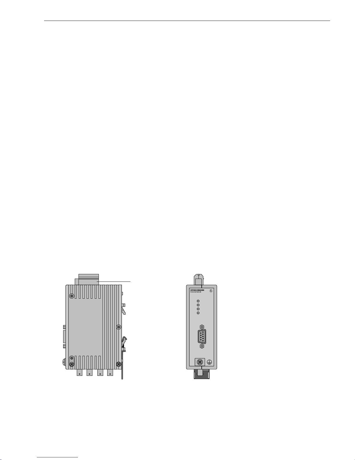
Port 1
System
Port 1
Port 2
Port 3
OZD FIP G3
5-pole
terminal block
for operating
voltage supply
and signaling
contact LED
indicators
Grounding
screw
Port 1
Electrical,
Sub-D
connector
Port 3
Optical,
BFOC/2,5
socket
Port 2
Optical,
BFOC/2,5
socket
Fig. 1: Fiber-optic FIP repeater OZD FIP G3. The illustration shows the position of the individual ports, the terminal block,
the LED indicators, and the grounding screw.

1 Introduction
6Version 1.0 11/97
Fiber-optic technology
The implementation of fiber-optic technology permits
very long transmission ranges and provides optimum
protection against EMI effects both along the trans-
mission link and (owing to the electrical isolation) at
the repeaters themselves.
Transmission rate
The fiber-optic FIP repeater OZD FIP G3 functions
at a transmission rate of 1 MBit/s (as defined in
EN 50 170).
Signal regeneration
The fiber-optic FIP repeater OZD FIP G3 regenerates
the signal shape and amplitude of the received data.
This function permits a maximum of 20 repeaters to
be cascaded via optical links.
FIP protocol
In a network topology as shown in Fig. 2, 3 and 4 (Ch. 2),
a response time must be taken into consideration at
the arbiter and in the data terminal equipment. The
data which is sent out, is returned to each optical port
by the neighboring device. This status signal is used
to monitor the output and the rings.
The response time is composed of the transfer time in
the optical fiber (5 ns/m) and the transfer time through
a repeater (< 1µs).
At a maximum transmission distance of 2.5 km, the
response time is as follows:
tresponse = 2 x 2500 m x 2 ns/m + 1 µs = 26 µs
If there is a break along the optical fiber, a predefined
waiting time of 30 µs is activated in the repeaters
affected by the fault (system LED red). This must be
taken into account when the system is planned.
Redundancy
Redundant signal transmission ensures a very high
degree of transmission reliability.
Redundant operating voltage supply can increase
operational reliability even further.
2.1 Redundant optical ring (two-fiber ring)
7
2 Network Topologies
Version 1.0 11/97
2 Network Topologies
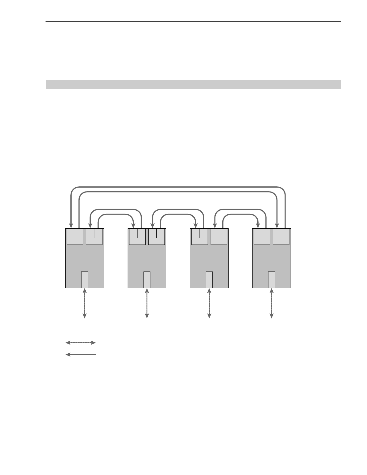
2.1 Redundant optical ring (two-fiber ring)
Fig. 2: Network structure in redundant optical two-fiber ring topology
FIP bus line
Fiber optic cable
Terminal unit(s)/
bus segment(s) Terminal unit(s)/
bus segment(s) Terminal unit(s)/
bus segment(s) Terminal unit(s)/
bus segment(s)
Port 3
SE
OZD FIP G3
Port 2
SE
Port 1
Port 3
SE
Port 2
SE
OZD FIP G3
Port 1
Port 3
SE
OZD FIP G3
Port 2
SE
Port 1
Port 3
SE
OZD FIP G3
Port 2
SE
Port 1
This network topology is used in the case of an optical
link between data terminal units or bus segments.
The implementation of a redundant link with OZD FIP
G3 repeaters ensures a high degree of reliability.
A maximum of 20 repeaters can be operated in one
optical ring.
The failure of an optical cable between any two
OZD FIP G3 repeaters does not affect the availability
of the network.
The repeaters detect total failure of an optical link. The
port LED of the faulty link is deactivated and the failure
is indicated by illumination of the red system LED and
response of the signaling contact.
It is advisable to install the duplex optical cables of
the two optical channels along different routes.

2 Network Topologies 2.1 Redundant optical ring (two-fiber ring)
8Version 1.0 11/97
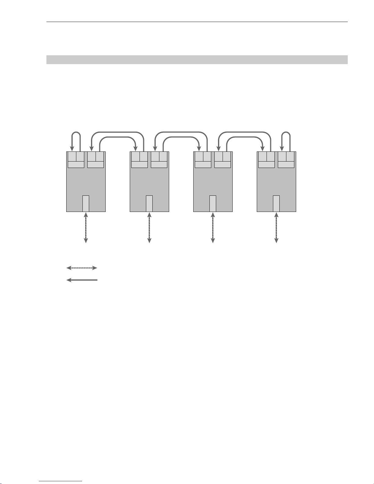
Fig. 3: Alternative wiring system for network structure in redundant optical two-fiber ring topology
FIP bus line
Fiber optic cable
Terminal unit(s)/
bus segment(s)
Port 3
SE
OZD FIP G3
Port 2
SE
Port 1
Terminal unit(s)/
bus segment(s)
Port 3
SE
OZD FIP G3
Port 2
SE
Port 1
Terminal unit(s)/
bus segment(s)
Port 3
SE
OZD FIP G3
Port 2
SE
Port 1
Terminal unit(s)/
bus segment(s)
Port 3
SE
OZD FIP G3
Port 2
SE
Port 1
Terminal unit(s)/
bus segment(s)
Port 3
SE
OZD FIP G3
Port 2
SE
Port 1
If problems are encountered with the configuration
of a redundant optical ring on account of excessively
long fiber-optic line sections, connections can also be
implemented as shown in Fig. 2.
In this case, each repeater is linked (in spatial terms)
with the next repeater but one. Two adjacent repea-
ters must be interconnected at the start and end of
every such line. This avoids individual “excessively
long“ fiber-optic line sections.
2.2 Line topology without redundancy
9
2 Network Topologies
Version 1.0 11/97
Fig. 4: Line topology without redundancy
FIP bus line
Fiber optic cable
Terminal unit(s)/
bus segment(s) Terminal unit(s)/
bus segment(s) Terminal unit(s)/
bus segment(s) Terminal unit(s)/
bus segment(s)
Port 3
SE
OZD FIP G3
Port 2
SE
Port 1
Port 3
SE
Port 2
SE
OZD FIP G3
Port 1
Port 3
SE
OZD FIP G3
Port 2
SE
Port 1
Port 3
SE
OZD FIP G3
Port 2
SE
Port 1
This network topology is used in the case of an optical
link between data terminal units or bus segments.
A maximum of 20 repeaters can be operated in an
optical line.
The first and last repeater in the line must be termi-
nated with an “optical short-circuit“ (see Fig. 4).
In this case, each input and output of the free ports
are connected to BFOC connectors via a short length
of optical cable.
2.2 Line topology without redundancy

2 Network Topologies
10 Version 1.0 11/97
Other manuals for OZD FIP G3
1
Table of contents
Other Hirschmann Repeater manuals

Hirschmann
Hirschmann OZD Genius G12 User manual

Hirschmann
Hirschmann OZD FIP G3 User manual

Hirschmann
Hirschmann OZD Profi 12M G12 PRO User manual

Hirschmann
Hirschmann OZD 485 G12 BAS User manual

Hirschmann
Hirschmann OZD Profi 12M User manual

Hirschmann
Hirschmann OZD 485 G12 PRO User manual

Hirschmann
Hirschmann OZD Profi 12M G11 User manual


