Hioki FT6031-03 User manual

EN
FT6031
EARTH TESTER
Instruction Manual
Oct. 2018 Revised edition 2
FT6031A981-02 18-10H
www.calcert.com [email protected]1.800.544.2843 0
5
10
15
20
25
30

i
Contents
Introduction.........................................................................1
Verifying Package Contents ..............................................1
Options (sold separately) ..................................................2
Safety Notes........................................................................3
Usage Notes........................................................................8
1 Overview 13
1.1 Overview and Features.................................13
Overview................................................................... 13
Features....................................................................13
1.2 Parts Names and Functions.........................15
1.3 How to Use Carrying Case ...........................20
2 How to Measure 21
2.1 MeasurementWorkow................................21
2.2 Attaching/Removing Protector ....................24
2.3 Inserting/Replacing Batteries ......................25
2.4 Inspection before Use...................................29
2.5 Setting Up Comparator (PASS/FAIL Test) ...31
How to set up comparator......................................... 32
How to disable comparator ....................................... 32
2.6 Precise Measurement for Earth
Resistance(Precise Measurement
Method, Three-pole Method) ........................33
Performing zero adjustment...................................... 35
Connecting measurement cables .............................36
Measuring earth resistance ......................................39
Stowing .....................................................................42
FT6031A981-02
www.calcert.com [email protected]1.800.544.2843 0
5
10
15
20
25
30

ii
2.7 SimpliedMeasurementforEarth
Resistance(SimpliedMeasurement
Method, Two-pole Method) ...........................44
Performing zero adjustment...................................... 46
Connecting test leads ...............................................48
Measuring earth resistance ......................................51
Stowing .....................................................................51
2.8 Cautions and Tips for Measurement ...........52
Distance between earthing electrodes...................... 52
Location to install auxiliary earthing rod.................... 53
How to insert / pull out auxiliary earthing rod............ 54
2.9 Auto Power Save
(Power-saving Function) ..............................56
2.10 Activating the LCD All-on Display ............... 56
2.11 Displaying the Serial number.......................57
3 Specication 59
3.1 GeneralSpecication ...................................59
3.2 Measurement Function/Performance..........61
4 Maintenance and Service 67
4.1 Repair, Inspection, and Cleaning.................67
4.2 Troubleshooting ............................................69
4.3 Error Display..................................................73
Appendix Appx. 1
Appendix 1 Earth Resistance ...................Appx. 1
Appendix 2 Measurement Principle .........Appx. 3
www.calcert.com [email protected]1.800.544.2843 0
5
10
15
20
25
30

1
Introduction
Introduction
Thank you for purchasing the HIOKI FT6031 Earth Tester. To obtain
maximum performance from the product, please read this manual
rst, and keep it handy for future reference.
Verifying Package Contents
When you receive the instrument, inspect it carefully to ensure
that no damage occurred during shipping. In particular, check the
accessories, panel switches, and connectors. If damage is evident,
or if it fails to operate according to the specications, contact your
authorized Hioki distributor or reseller.
Check the package contents as follows.
FT6031
Accessory
L9840
Auxiliary Earthing Rod (2 piece set) ×1
L9841 Measurement Cable
(alligator clip, black 4 m) ×1
L9842-11 Measurement Cable
(yellow 10 m, equipped with winder) ×1
L9842-22 Measurement Cable
(red 20 m, equipped with winder) ×1
C0106 Carrying Case ×1
Protector
LR6 Alkaline battery × 4
Instruction manual
www.calcert.com [email protected]1.800.544.2843 0
5
10
15
20
25
30

2
Options (sold separately)
Options (sold separately)
The following options are available for the instrument. Contact your
authorized Hioki distributor or reseller when ordering.
L9787 Test Lead
(for simplied measurement method,
indoor use only, red and black 1.2 m each)
L9840 Auxiliary Earthing Rod
(for precision measurement method, 2 pcs in 1 set)
(φ 6 mm, entire length of 270 mm, straight
section 235 mm, material: stainless SUS304)
L9841 Measurement Cable
(for precision measurement method,
alligator clip, black 4 m)
L9842-11 Measurement Cable
(for precision measurement method,
yellow 10 m, equipped with winder)
L9842-22 Measurement Cable
(for precision measurement method,
red 20 m, equipped with winder)
L9843-51 Measurement Cable
(for precision measurement method,
yellow 50 m, equipped with at cable winder)
L9843-52 Measurement Cable
(for precision measurement method,
red 50 m, equipped with at cable winder)
L9844 Measurement Cable
(for earthing terminal board, alligator clip,
3 cables in 1 set, red/yellow/black 1.2 m each)
9050 Earth Nets
(2 sheets in 1 set, 300 mm × 300 mm)
C0106 Carrying Case
www.calcert.com [email protected]1.800.544.2843 0
5
10
15
20
25
30

3
Safety Notes
Safety Notes
This instrument is designed to conform to IEC 61010 Safety
Standards, and has been thoroughly tested for safety prior to
shipment. However, using the instrument in a way not described in
this manual may negate the provided safety features.
Before using the instrument, be certain to carefully read the following
safety notes.
DANGER
Mishandling during use could result in injury or death,
as well as damage to the instrument. Be certain that
you understand the instructions and precautions in
the manual before use.
WARNING
With regard to the electricity supply, there are risks
of electric shock, heat generation, re, and arc
discharge due to short circuits. If persons unfamiliar
with electricity measuring instruments are to use
the instrument, another person familiar with such
instruments must supervise operations.
www.calcert.com [email protected]1.800.544.2843 0
5
10
15
20
25
30

4
Safety Notes
Notation
In this manual, the risk seriousness and the hazard levels are classied as
follows.
DANGER
Indicates an imminently hazardous situation
that will result in death or serious injury to the
operator.
WARNING
Indicates a potentially hazardous situation
that may result in death or serious injury to the
operator.
CAUTION
Indicates a potentially hazardous situation
that may result in minor or moderate injury to
the operator or damage to the instrument or
malfunction.
IMPORTANT
Indicates information related to the operation
of the instrument or maintenance tasks with
which the operators must be fully familiar.
Indicates a high voltage hazard.
If a particular safety check is not performed or
the instrument is mishandled, this may give
rise to a hazardous situation; the operator
may receive an electric shock, may get burnt
or may even be fatally injured.
Indicates prohibited actions.
Indicates the action which must be performed.
*Additional information is presented below.
www.calcert.com [email protected]1.800.544.2843 0
5
10
15
20
25
30
5
Safety Notes
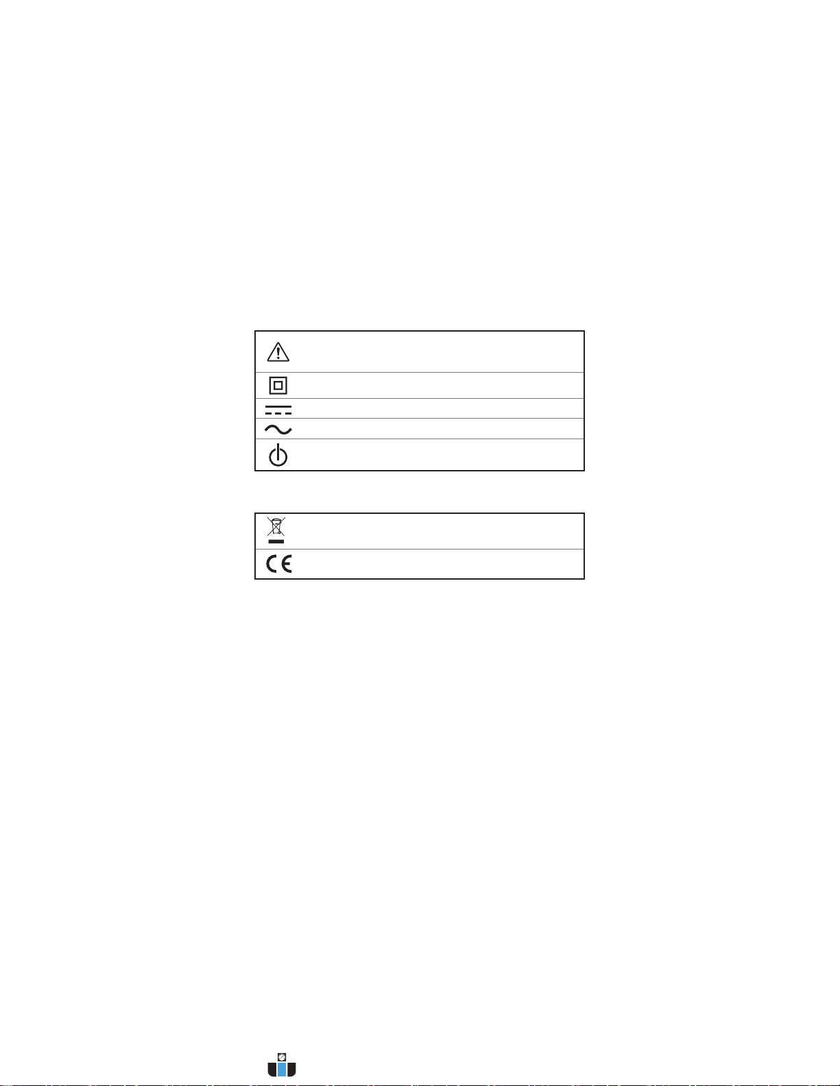
Symbols afxed to the instrument
Indicates cautions and hazards. When the symbol is printed on
the instrument, refer to a corresponding topic in the Instruction
Manual.
Indicates a double-insulated device.
Indicates DC (Direct Current).
Indicates AC (Alternating Current).
Indicates the power switch mark.
Symbols for various standards
Indicates the Waste Electrical and Electronic Equipment
Directive (WEEE Directive) in EU member states.
Indicates that the instrument conforms to safety regulations set
out by the EC Directive.
www.calcert.com [email protected]1.800.544.2843 0
5
10
15
20
25
30

6
Safety Notes
Screen display
This instrument uses the following screen displays.
1 2 3 4 5 6 7 8 9 0
A B C D E F G H I J K L M N O P Q R S T U V W X Y Z
Accuracy
We dene measurement tolerances in terms of f.s. (full scale), rdg.
(reading) and dgt. (digit) values, with the following meanings:
f.s. (Maximum display value)
The maximum displayable value.
rdg.
(Reading or displayed value)
The value currently being measured and indicated on the
measuring instrument.
dgt.
(Resolution)
The smallest displayable unit on a digital measuring
instrument, i.e., the input value that causes the digital display
to show a “1” as the least-signicant digit.
www.calcert.com [email protected]1.800.544.2843 0
5
10
15
20
25
30

7
Safety Notes
Measurement categories
To ensure safe operation of measuring instruments, IEC 61010
establishes safety standards for various electrical environments,
categorized as CAT II to CAT IV, and called measurement categories.
DANGER
•Using a measuring instrument in an environment
designated with a higher-numbered category than
that for which the instrument is rated could result in
a severe accident, and must be carefully avoided.
•Using a measuring instrument without categories in
an environment designated with the CAT II to CAT
IV category could result in a severe accident, and
must be carefully avoided.
This instrument conforms to the safety requirements for CAT II 300 V, CAT III
150 V, CAT IV 100 V measuring instruments.
CAT II: When directly measuring the electrical outlet receptacles of
the primary electrical circuits in equipment connected to an
AC electrical outlet by a power cord (portable tools, household
appliances, etc.).
CAT III: When measuring the primary electrical circuits of heavy equipment
(xed installations) connected directly to the distribution panel,
and feeders from the distribution panel to outlets.
CAT IV: When measuring the circuit from the service drop to the service
entrance, and to the power meter and primary overcurrent
protection device (distribution panel).
Outlet
CAT II
Internal Wiring
Distribution Panel
Service Entrance
Service Drop
CAT IV
Power Meter
CAT III
Fixed Installation
www.calcert.com [email protected]1.800.544.2843 0
5
10
15
20
25
30
This manual suits for next models
2
Table of contents
Other Hioki Test Equipment manuals


Hioki
Hioki RM3543 User manual

Hioki
Hioki 3665-20 User manual

Hioki
Hioki MEMORY HiCORDER 8855 User manual

Hioki
Hioki IR3455 User manual

Hioki
Hioki ST5520-01 User manual

Hioki
Hioki FT3405 User manual

Hioki
Hioki 3288 User manual

Hioki
Hioki 9455 User manual

Hioki
Hioki 3561 User manual

Hioki
Hioki 3665-20 User manual


Popular Test Equipment manuals by other brands


PCB Piezotronics
PCB Piezotronics 8159-0112A Installation and operating manual

BW Technologies
BW Technologies MicroDock II user manual

Sun Nuclear
Sun Nuclear 1027 user guide

Biomark
Biomark HPR LITE READER user manual

Ashcroft
Ashcroft ATE-100 operating manual

Rohde & Schwarz
Rohde & Schwarz RTA4000 user manual