INSTALLATION AND OPERATING INSTRUCTIONS
72-0112 03-06-18 7013500 314 SKLT 69 A
Page 3
WARNING
SECTION 2: MOUNTING OF SAUNA HEATER
SECTION 3: PLACING OF ROCKS (SEE DIAGRAMS #10 and 11)
-NOTE: Complete electrical connections and test the heater prior to this step.
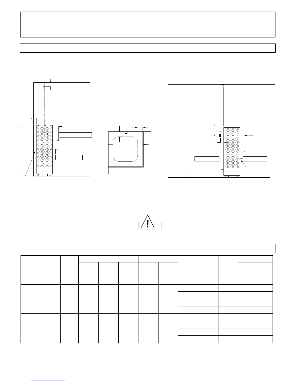
Attach wall bracket to any of the mounting holes located on either side of the spine on the
rear of the heater shroud (reference diagram 4). Slide heater into position, according to
dimensions shown in Diagram 1 and mark locations for the two mounting screws. Slide
heater forward and screw two 1/4” x 1” lag bolts into sauna wall at locations marked
earlier, leaving approximately 1/8” of bolt shoulder exposed so bracket can easily slide over
bolt heads. Re-locate heater into position with key-holes of bracket locking onto lag bolts.
Adjust the leveling feet to ensure that the heater is vertical. Use a level on two sides of
heater to verify plumb.
If mounting heater in center of room, use same procedure described above but locate
mounting bracket so that it can attach to the bench framing that surrounds the heater.
The rocks supplied have been chosen to provide the best heater performance. Use of any
other type of rock may void the heaters warranty. Never operate the heater without rocks
in place! Rinse the rocks with water before placing in the heater.
Install the BWT (Bio Water Technique) tank between the second and third heating
elements resting on the top of the elements. (See diagram 11) The BWT tank has slots in
the outer ange that will align with the element loops. Install the BWT cover and the round
herb cup.
Start inserting rocks into the heater in even layers so that the 3 heating elements remain
as vertical and evenly spaced as possible. Continue to randomly drop rocks into the
heater until you are even with the top of the heating coils. Add one more loose layer to
cover up the elements and top of the BWT. (Do Not Cover Up the round herb cub on top
of the BWT!) The rocks must fully cover the heating elements. Attach the guard with the
screws provided. See Diagram #10 & 11 for rock placement.
Packing the rocks too tightly may cause the heater high limit switch to trip.
Fire sprinkler systems used
inside any sauna room should
be properly rated for sauna
room temperatures.
Do not place hands
and or arms over the BWT
when hot. Steam from BWT
may cause severe burns.
Do not pour chlorinated pool
or spa water on heater or in
the BWT.
Excessive water use on heater
may cause damage and void
warranty.
Electric Shock Hazard - High
voltage exists within this
equipment. There are no user
serviceable parts in this
equipment. All installation
and service to this equipment
should be performed by
qualied licensed personnel
in accordance with local and
national codes.
Do not construct sauna room
so as to restrict air ow
through the bottom of the
heater.
Packing the rocks too tightly
may cause the heater high
limit switch to trip.
SECTION 4: ELECTRICAL HOOK-UP
Electrical installation must be made by a licensed electrician in accordance with the
National Electrical Code and local regulations.
- NOTE: A GFCI (Ground Fault Circuit Interrupt) device is not required by ETL. A GFCI may
be installed if required by local codes but will nuisance trip during use of the product. -
CAUTION: Loose wire connections can cause heat damage to wires, terminal blocks and
other components and may void the warranty.
Remove the screws from the left and right sides of the electrical box. Remove the painted
trim piece from the front of the box. Route the feed wires through the holes provided in the
bottom of the heater and connect the wires to the terminal block. To determine the correct
wire size, refer to Diagram 2. Use copper supply wire only, suitable for minimum 90
degrees C. The heater must be grounded! See Diagram 6 for proper connections.
SECTION 5: TEMPERATURE SENSOR
Feed the "low voltage" sensor wire from the sensor to the sauna heater location. Sensor
wire must be routed completely separate (as per low voltage electrical wiring codes) from
any wiring carrying over 50 volts. It may be necessary to drill holes to string the wire
through the studs or ceiling joists. Route the wire to bottom of the heater and connect to
the sensor connection. Mount sensor to nished wall 3" from the ceiling directly above
the heater using two (2) screws (provided) as shown in diagrams 1, 3 & 5.
If mounting heater in the middle of your sauna room, locate the temperature sensor on the
ceiling above the heater at a point directly above one outer edge of the sauna heater
shroud. See Diagram 1.