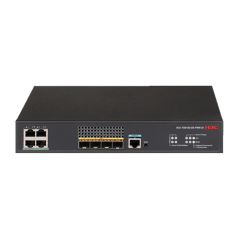
H3C S9500 Series User manual

Installation Manual
H3C S9500 Series Routing Switches Table of Contents
i
Table of Contents
Chapter 3 Installing the Switch .......................................................................... 3-1
3.1 Installation Flow....................................................................................... 3-1
3.2 Confirming Installation Preparation ........................................................... 3-1
3.3 Mounting the Switch in a Rack.................................................................. 3-2
3.3.1 Preparations ................................................................................... 3-2
3.3.2 Installing the Cable Management Bracket and Rack-Mounting Ears .. 3-2
3.3.3 Mounting the Switch........................................................................ 3-3
3.3.4 Verifying the Installation.................................................................. 3-3
3.4 Installing the Switch on a Workbench........................................................ 3-4
3.4.1 Preparations ................................................................................... 3-4
3.4.2 Procedure....................................................................................... 3-4
3.5 Connecting the PGND Wire ...................................................................... 3-4
3.5.1 In a common grounding environment ............................................... 3-5
3.5.2 In other Grounding Environments .................................................... 3-5
3.6 Installing a PSU....................................................................................... 3-9
3.6.1 Installation Preparation ................................................................... 3-9
3.6.2 Installation Procedure ..................................................................... 3-9
3.6.3 Connecting Power Cable(s)............................................................ 3-11
3.7 Installing a Board.................................................................................... 3-15
3.7.1 Installation Preparations ................................................................ 3-15
3.7.2 Installation Procedure .................................................................... 3-16
3.8 Installing PoE Power Supply....................................................................3-16
3.8.1 Installation Procedure .................................................................... 3-17
3.8.2 Installing the PoE Power Entry Module ........................................... 3-17
3.8.3 Connecting PoE Power Cables ....................................................... 3-18
3.9 Connecting Interface Cables.................................................................... 3-20
3.9.1 Cable Routing Recommendations ...................................................3-20
3.9.2 Connecting Console Cable ............................................................. 3-21
3.9.3 Connecting the AUX Cable............................................................. 3-23
3.9.4 Connecting Network Cables ........................................................... 3-23
3.9.5 Connecting Fiber ........................................................................... 3-23
3.10 Verifying the Installation........................................................................ 3-27

Installation Manual
H3C S9500 Series Routing Switches Chapter 3 Installing the Switch
3-1
Chapter 3 Installing the Switch
The S9500 series are designed for indoor applications.
Warning:
Do not touch any exposed wires, terminals or any parts labelled with a
high-voltage hazard warning to avoid bodily injury.
3.1 Installation Flow
Start
Confirm installation preparation
Confirm installation position
Mount the switch in a rack Install the switch on a workbench
Install a PSU
Install boards
Install PoE power supply
(optional)
Connect the PGND wire
Finish
Verify the installation
Connect interface cables
Figure 3-1 Installation flow
3.2 Confirming Installation Preparation
zMake sure that you have read Chapter 2 Preparing for the Installation
carefully.

Installation Manual
H3C S9500 Series Routing Switches Chapter 3 Installing the Switch
3-2
zAll requirements mentioned in Chapter 2 Preparing for the Installation
have been met.
3.3 Mounting the Switch in a Rack
3.3.1 Preparations
Before installation, make sure that:
zThe cabinet is grounded and stable. The layout inside the cabinet for
switch installation has been well done and there is no obstacle inside
or around the cabinet.
zThe switch is ready for installation and has been carried to a place
near the cabinet.
3.3.2 Installing the Cable Management Bracket and Rack-Mounting
Ears
For your convenience, a cable management bracket is shipped with the
S9500 series. Take the following steps to install the cable management
bracket.
1) Facing the LPU slots of the switch, insert the shipped cable
management bracket into the left rack-mounting ear on which there is
a recessed hole for installing the cable management bracket, and fix it
with screws. (One cable management bracket for the
S9505/S9508/S9508V and two for the S9512).
2) Install the rack-mounting ears onto the both sides of the switch, as
shown in Figure 3-2.
Figure 3-2 Install the cable management bracket and rack-mounting ears

Installation Manual
H3C S9500 Series Routing Switches Chapter 3 Installing the Switch
3-3
3.3.3 Mounting the Switch
Note:
Make sure that supports have been installed in corresponding positions
and the supports can bear the switch weight.
1) Two people are required to lift the switch. Put the switch on the
supports and slide it into the cabinet until the rack-mounting ears
touch against the front square-holed columns.
2) Fix the rack mounting ears onto the square-holed columns with
screws.
Figure 3-3 Install the switch into a standard 19-inch rack
3.3.4 Verifying the Installation
After installing the switch into the rack, check the items listed in Table 3-1.
Table 3-1 Checklist for switch installation
Result
Item Yes No Remarks
The cable management bracket is well fixed
on the left rack-mounting ear.

Installation Manual
H3C S9500 Series Routing Switches Chapter 3 Installing the Switch
3-4
Result
Item Yes No Remarks
The rack-mounting ears are well fixed on the
switch.
The installation position is right.
The rack-mounting ears are well fixed on the
rack
3.4 Installing the Switch on a Workbench
When no 19-inch cabinet is available, you can place the switch on a clean
and stable workbench.
3.4.1 Preparations
zMake sure that the workbench is sturdy enough to bear the weight of
the switch and cables.
zMake sure that the workbench is flat and well grounded.
3.4.2 Procedure
Lift the switch onto the workbench with another person.
Caution:
Reserve at least 15.2 cm (6.0 in.) of clearance around the switch for heat
dissipation.
3.5 Connecting the PGND Wire
Caution:
For the safety of operators and equipment, the switch must be well
grounded. The resistance reading between switch chassis and the ground
must be less than 1 ohm.

Installation Manual
H3C S9500 Series Routing Switches Chapter 3 Installing the Switch
3-5
3.5.1 In a common grounding environment
Follow these steps to connect the PGND wire in a common grounding
environment:
1) Remove the screw from the grounding hole in the switch chassis.
2) Wear the connector of the PGND wire accompanied with the switch on
the grounding screw.
3) Insert the grounding screw into the grounding hole and screw it down.
4) Connect the other end of the PGND wire to the ground barof the switch,
as shown in Figure 3-4.
Figure 3-4 Connect the PGND wire
Note:
Generally, the cabinets installed in equipment rooms are equipped with
ground bar. In this case, you can connect the PGND wire of the switch to
the ground bar for it.
3.5.2 In other Grounding Environments
The following are some methods for grounding the switch in different
grounding environments.

Installation Manual
H3C S9500 Series Routing Switches Chapter 3 Installing the Switch
3-6
Note:
Rather than specifying the switch model or showing the actual location of
the switch power input or grounding screw, the following figures are
primarily intended for illustrating the switch grounding, either via
grounding screw or power input, in specific grounding environments.
zIf a ground bar is available, attach one end of the yellow-green PGND
wire of the switch to a grounding bolt of the ground bar and fasten the
captive screws.
Caution:
Note that neither the fire hydrant nor lightning rod of a building is suitable
for grounding the switch. The PGND wire of the switch should be
connected to the grounding device in the equipment room. (For the S9500
series, the grounding screw is on the rear panel. Connect it as illustrated in
Figure 3-5).
(4)
(1) (2)
(3)
(4)
(1) (2)
(3)
(1) Rear panel of the switch (2) Grounding screw
(3) PGND wire (4) Ground bar of the equipment room
Figure 3-5 Ground the switch when a ground bar is available

Installation Manual
H3C S9500 Series Routing Switches Chapter 3 Installing the Switch
3-7
zIf there is no ground bar but earth nearby and the grounding body is
allowed to be buried, you can simply hammer an angle iron or steel
pipe no shorter than 0.5 m into the earth.
Caution:
The yellow-green PGND wire should be welded with the angle iron (steel
pipe) and the joint should be processed against eroding. (For the S9500
series, the grounding screw is on the rear panel. Connect it as illustrated in
Figure 3-5).
(3)
(4)
(5)
(1)
(2)
(3)
(4)
(5)
(1)
(2)
(1) Rear panel of the switch (2) Grounding screw
(3) PGND wire (4) Ground
(5) Angle steel (steel pipe)
Figure 3-6 Ground the switch when allowed to bury grounding body
nearby
zIf both ground bar and the conditions for burying the grounding body
are not available, an AC-powered Ethernet switch can be grounded
using the PE wire of the AC power supply.

Installation Manual
H3C S9500 Series Routing Switches Chapter 3 Installing the Switch
3-8
Caution:
Make sure that the PE wire of the AC power supply has been well grounded
at the side of the power distribution room or AC power supply transformer.
(3)
(5)
(4)
(1)
(2)
(3)
(5)
(4)
(3)
(5)
(4)
(1)
(2)
(1) Front panel of the switch (2) AC power input
(3) 3-core AC power cord (4) Transformer
(5) Protection earth (PE) wire
Figure 3-7 Ground the switch through the AC PE wire
zIf no ground bar or condition for burying the grounding body is
available, a DC-powered Ethernet switch can be grounded through the
PGND strip of the power distribution frame (PDF).
Caution:
Make sure the RTN wire is well connected to the ground at the DC output
of the PDF.

Installation Manual
H3C S9500 Series Routing Switches Chapter 3 Installing the Switch
3-9
(1)
(2)
(6)
(3)
(4)
(7)
(8)
(9)
(12)
(5) (11)
(10)
(1)
(2)
(6)
(3)
(4)
(7)
(8)
(9)
(12)
(5) (11)
(10)
(1) Front panel of the
switch (2) DC power input (3) NEG terminal
(4) RTN terminal (5) PDF (6) -48V strip
(7) RTN strip (8) PGND strip (9) Earth ground
(10) PGND wire (11) Grounding screw (12) Rear panel of the
switch
Figure 3-8 Ground the switch through the PGND strip of the PDF
3.6 Installing a PSU
3.6.1 Installation Preparation
zWear an ESD-preventive wrist strap and verify the ESD-preventive
wrist strap is properly grounded.
zIf there is a filler panel in the position where you will install a PSU,
remove the filler panel.
Caution:
When you move a PSU, hold its bottom with one hand. Do not move it by
just holding its handle. Otherwise, the PSU may be damaged.
3.6.2 Installation Procedure
I. Removing a PSU other than NEPS3500-A
The following procedure applies to all NEPS PSUs except NEPS3500-A.
Other manuals for S9500 Series
73
Table of contents
Other H3C Switch manuals

H3C
H3C S9500 Series User manual

H3C
H3C S7500X Series User manual

H3C
H3C S3600V3 Series Instruction Manual

H3C
H3C S5830V2 series User manual

H3C
H3C S7500 Series User manual

H3C
H3C S9500E Series User manual

H3C
H3C S5830V2 series User manual

H3C
H3C S12500X-2L User manual

H3C
H3C S12500-X User manual

H3C
H3C S10500X Series User manual

H3C
H3C S3610 Series User manual

H3C
H3C S6116 Series User manual

H3C
H3C EPON OLT User manual

H3C
H3C S3610 Series Installation instructions

H3C
H3C S6820-56HF Operating and maintenance manual

H3C
H3C H3C S5100-SI User manual

H3C
H3C S12500X-2L User manual

H3C
H3C S6800-2C Operating and maintenance manual

H3C
H3C S5500-28C-EI User manual

H3C
H3C S6800-54QF User manual