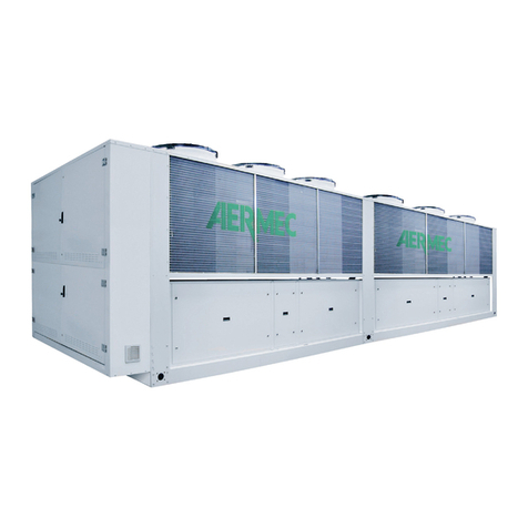
Gree B Series User manual

Service Manual
Change for life
B series modular air-cooled scroll chiller (heat pump)
T1/ R410A /50Hz
Thank you for choosing commercial air conditioners.Please
read this Owner’ s Manual carefully before operation and
If you have lost the Owner's Manual, please contact the
local agent or visit www.gree.com or send an email to

Contents
PRODUCT ........................................................................................................3
1 Introduction ....................................................................................................3
1.1 Lineup.....................................................................................................3
1.2 Nomenclature .........................................................................................3
1.3 Product features .....................................................................................4
1.4 Nominal operating conditions..................................................................4
1.5 Operation range......................................................................................5
2 Unit performance curves................................................................................5
3 Working principle ...........................................................................................6
4 Techinical parameters list...............................................................................6
4.1 Electrical parameters ..............................................................................6
4.2 Performance parameters table................................................................7
4.3 Scope of supply ......................................................................................8
DESIGN AND SELECTION.............................................................................10
UNIT CONTROL .............................................................................................15
1 Schematic diagram ......................................................................................15
2 Operation owchart......................................................................................17
2.1 Cooling .................................................................................................17
2.2 Heating .................................................................................................18
3 Key control logics.........................................................................................19
3.1 Cooling control......................................................................................19
3.2 Heating control......................................................................................19
3.3 Automatic anti-freezing operation..........................................................20
3.4 Control to the compressor.....................................................................20
3.5 Control to the fan ..................................................................................20
3.6 Control to the 4–way valve....................................................................20
3.7 Control to the water pump.....................................................................20
3.8 Control to the electronic expansion valve .............................................20
3.9 Protection..............................................................................................20

4 General introduction.....................................................................................21
4.1 Homepage ............................................................................................22
4.2 Menu page............................................................................................23
4.3 Introduction to the pop-up windows ......................................................24
4.4 Backlight ...............................................................................................24
5 Operation instructions ..................................................................................25
5.1 On/Off ...................................................................................................25
5.2 Functions ..............................................................................................26
5.3 Parameter .............................................................................................34
5.4 Information............................................................................................36
5.5 E-Clear .................................................................................................44
5.6 General.................................................................................................45
5.7 Setup of DIP switches on the motherboard...........................................48
6 Smart management system .........................................................................49
6.1 Long-distance monitoring/BMS interface ..............................................49
6.2 Network of the long-distance monitoring system...................................49
6.3 Hardware ..............................................................................................50
6.4 Model selection instructions..................................................................51
UNIT INSTALLATION......................................................................................54
1 Installation owchart ....................................................................................54
2 Preparations before installation....................................................................55
2.1 Precautions for installation....................................................................55
2.2 Importance of installation ......................................................................56
2.3 Selection of installation materials..........................................................57
3 Tools ............................................................................................................62
3.1 Cutting and nishing tools.....................................................................62
3.2 Measuring tools ....................................................................................62
4 Installation instructions.................................................................................64
4.1 Outline dimensions ...............................................................................64
4.2 precautions for installation ....................................................................65

4.3 Installation environment ........................................................................65
4.4 Installation and service space...............................................................65
4.5 Installation foundation...........................................................................66
4.6 Handling and lifting ...............................................................................66
4.7 Placement of the main unit ...................................................................67
5 Piping and insulation....................................................................................68
5.1 Installation of the water system.............................................................68
5.2 Requirements on piping ........................................................................70
5.3 Installation of the expansion tank..........................................................78
5.4 Installation of condensate pipes............................................................79
6 Electric wiring...............................................................................................81
6.1 Safety precautions ................................................................................81
6.2 Control concept.....................................................................................81
6.3 Specication of power supply................................................................83
6.4 Wiring of the electric control cabinet .....................................................84
6.5 Filed wiring............................................................................................86
6.6 Networking and wiring between units....................................................87
6.7 Electric wiring digram............................................................................89
6.8 Jumpers................................................................................................91
TEST OPERATION, TROUBLESHOOTING AND MAINTENANCE ................93
1 Commissioning ............................................................................................93
1.1 Flowchart of commissioning..................................................................93
1.2 Safety precautions for commissioning...................................................93
1.3 Preparation before commissioning........................................................93
1.4 Check before commissioning ................................................................94
1.5 Check for initial run ...............................................................................95
2 Troubleshooting ...........................................................................................97
2.1 View on errors.......................................................................................97
2.2 Error list ................................................................................................99
2.3 Errors identifying of systems...............................................................100
2.4 Flow chart of troubleshooting..............................................................102
2.5 Error identifying of controller ...............................................................107

3 Power distribution ......................................................................................109
3.1 Power distribution logic .......................................................................109
3.2 Introduction to the main electric element ............................................110
4 Replacement of main parts ........................................................................110
4.1 Brief introduction.................................................................................110
4.2 Replacement instructions....................................................................112
5 Routine maintenance .................................................................................120
5.1 Repairs to refrigerant leakage.............................................................120
5.2 Air removal..........................................................................................121
6 Exploded views and part lists.....................................................................122
7 Maintenance ..............................................................................................127
7.1 Requirements for maintenance ...........................................................127
7.2 Freeze protection in winter..................................................................129

1
SAFETY NOTICE
The following symbols are used in this document to alert the reader to potential of hazard.
WARNING indicates a potentially hazardous situation which, if not avoided, could result in damage
to the machine as well as death or serious injury.
CAUTION identies a hazard which could lead to minimal or moderate damage to the machine as
well as death or serious injury.
BAN indicates a potentially hazardous situation which, if not avoided, could result in death or
serious injury.
COMPLIANCE identies a hazard which could lead death or serious injury as well as damage to the
property.
PREFACE
Thank you for selecting Gree’s B series inverter modular air-cooled chiller (heat pump). Please read
this service manual carefully before installing and using the product and achieve operating effect. We
hereby instruct as below:
The Manual is applied to B series inverter modular air-cooled chiller (heat pump), specifying operation
safety requirements, basic principles and implementation approaches for construction fulfillment,
construction debug, after-sale maintenance and repairs. All works must be performed in accordance with
the relevant national (and local) safety requirements and User's Manual, which if not abided, could result
in potential damage to the air conditioner, and even serious injury or death.

2
Product
Product

3
Product
PRODUCT
1 Introduction
1.1 Lineup
Model
Cooling
capacity
Heating
capacity Power supply Refrigerant Diagram
kW kW
LSQWRF65VM/NaB-X 65 70
380-415VAC
3Ph 50Hz/60Hz R410A
LSQWRF130VM/NaB-X 130 140
1.2 Nomenclature
LS QW R F 65 V M / Na B - X
1 2 3 4 5 6 7 8 9 10
No. Code description Options
1Unit LS: chiller
2Compressor type QW: hermetic scroll/rotor type
3Unit function Default:cooling only
R: heat pump
4Cooling method of condenser F: air-cooled
5Rated cooling capacity Rated cooling capacity = number (kW)
6Variable frequency Default: xed speed
7Assembly method M: modular
8Refrigerant type Na: R410A
9Design code A-Z alphabetic order
10 Power code 380-415VAC 3Ph 50Hz/60Hz
For instance, LSQWRF65VM/NaB-X indicates an inverter modular air-cooled chiller with a fully
enclosed rotor-type compressor, featuring 65kW cooling capacity and using R410A refrigerant (Lengshui,
Quanfengbi, Woxuan/Zhuanzi, Rebeng, Fengleng, 60kW, Variable spped, Modular, R410A, A, 380-
415VAC 3Ph 50Hz/60Hz).

4
Product
1.3 Product features
The all-inverter modular air-cooled chillers work outstandingly by virtue of their major features stated
below.
(1) High efciency and energy saving
The variable-frequency all-round direct current technology enables the unit to make accurate control of
itself to operate at a optimum frequency in light of load changes. With shell-and-tube heat exchangers and
ns, the unit rated at beyond the national rst level.
At the energy saving mode, the unit will estimate the load automatically in accordance with the needs
of users to operate at an excellent status.
(2) Wide operating range
The unit is able to work for cooling in the ambient temperature ranging from -15°C to 48°C all year
round, for heating in the ambient temperature ranging from -20°C to 40°C.
(3) High reliability
While its compressor maintains equilibrium running, the states of all compressors are recorded, and
compressor runtime is adjusted to prevent overload of operation.
Major and subordinate water pumps are ready to change their roles, improving the unit adaptability. A
pump fault will not affect the entire unit operation.
Controlled by a micro computer, the unit is going to run in safe with a self-diagnosis function and
protection machanism such as high/low pressure protection of compressor, freeze protection, temperature
sensor protection.
(4) Exceeding quietness
The high-efficiency and low-noise fan blades and motor as well as the optimized air passage can
greatly lower operation noise of the unit. Besides, the quite mode can provide the user a ultra-quite
environment.
(5) Smart control
A module malfunction will not bother the other modules. Any module can act as a master or servant to
achieve mutual assistance.
The building monitoring system (BMS) helps users to manage and coordinate no more than 255 units,
providing functions like remote ON/OFF, remote parameter setting and alarm reminder.
Fexible coordination of no more than 16 identical or different modules constitutes total cooling capacity
ranging from 65kW to 1040kW.
1.4 Nominal operating conditions
Item
Water side Air side
Water ow
m3/(h·kW) Outlet temparature (°C) Dry bulb
temperature (°C)
Wet bulb
temperature (°C)
Cooling
0.172
7 35 -
Heat pump 45 7 6

5
Product
1.5 Operation range
The unit should work within the specied operation range as shown in the table below:
Item
Water side Air side
Leaving water
temperature (°C)
Water temperature
difference (°C)
Ambient DB
temperature (°C)
Cooling 5~20 2.5~6 -15~48
Heating 35~50 2.5~6 -20~40
2 Unit performance curves
Here are curves indicating the unit performances in cooling and heating states.
LSQWRF65VM/NaB-X LSQWRF65VM/NaB-X
Cooling Heating
Capacity (kW)
Capacity (kW)
Leaving water temperature (°C) Leaving water temperature (°C)
Ambient temperature (°C)
Ambient temperature (°C)
LSQWRF130VM/NaB-X LSQWRF130VM/NaB-X
Cooling Heating
Leaving water temperature (°C)
Leaving water temperature (°C)
Capacity (kW)
Ambient temperature (°C)
Capacity (kW)
Ambient temperature (°C)
This manual suits for next models
2
Table of contents
Other Gree Chiller manuals

Gree
Gree EVO Series User manual

Gree
Gree C Series User manual

Gree
Gree T1/R22 User manual

Gree
Gree A Series User manual

Gree
Gree LSQWRF35VM/NhA-M User manual

Gree
Gree FB01 User manual

Gree
Gree LSQWRF35VM/NaA-M User manual

Gree
Gree GK-C03TC1AD User manual

Gree
Gree T1/R410A/50Hz User manual

Gree
Gree LSQWF65M/N-M User manual


Popular Chiller manuals by other brands


Moffat
Moffat Friginox TSR-11SC Specification sheet

Denali
Denali M1 user manual

MP Systems
MP Systems PURGE Series manual

AEC
AEC PCA SERIES Operation and installation manual

Carrier
Carrier AquaEdge 19XRV series Start-up and service instructions

Telemark
Telemark TVP-2000 Operation, installation and service manual