Graco 25M712 User manual

For use on RoadPak™Line Striping Systems to steer the gun arm during spray operation.
For Professional use only.
Model 25M712
Important Safety Instructions
Read all warnings and instructions in this manual and in related manuals.
Be familiar with the controls and the proper usage of the equipment.
Save these instructions.
Related Manuals:
3A5384 Operation
3A5407B
EN
Instructions
Steerable Carriage Kit for RoadLazer™and RoadPak™
Line Striping Systems

Warnings
23A5407B
Warnings
The following warnings are for the setup, use, grounding, maintenance, and repair of this equipment. The exclamation
point symbol alerts you to a general warning and the hazard symbols refer to procedure-specific risks. When these sym-
bols appear in the body of this manual or on warning labels, refer back to these Warnings. Product-specific hazard sym-
bols and warnings not covered in this section may appear throughout the body of this manual where applicable.
FIRE AND EXPLOSION HAZARD
Flammable fumes, such as solvent and paint fumes, in work area can ignite or explode. Paint or solvent
flowing through the equipment can cause static sparking. To help prevent fire and explosion:
• Use equipment only in well-ventilated area.
• Eliminate all ignition sources; such as pilot lights, cigarettes, portable electric lamps, and plastic drop cloths
(potential static sparking).
• Ground all equipment in the work area. See Grounding instructions.
• Never spray or flush solvent at high pressure.
• Keep work area free of debris, including solvent, rags and gasoline.
• Do not plug or unplug power cords, or turn power or light switches on or off when flammable fumes are
present.
• Use only grounded hoses.
•Stop operation immediately if static sparking occurs or you feel a shock. Do not use equipment until you
identify and correct the problem.
• Keep a working fire extinguisher in the work area.
ENTANGLEMENT HAZARD
Rotating parts can cause serious injury.
• Keep clear of moving parts.
• Do not operate equipment with protective guards or covers removed.
• Do not wear loose clothing, jewelry or long hair while operating equipment.
• Equipment can start without warning. Before checking, moving, or servicing equipment, follow the
Pressure Relief Procedure and disconnect all power sources.

Installation
3A5407B 3
Installation
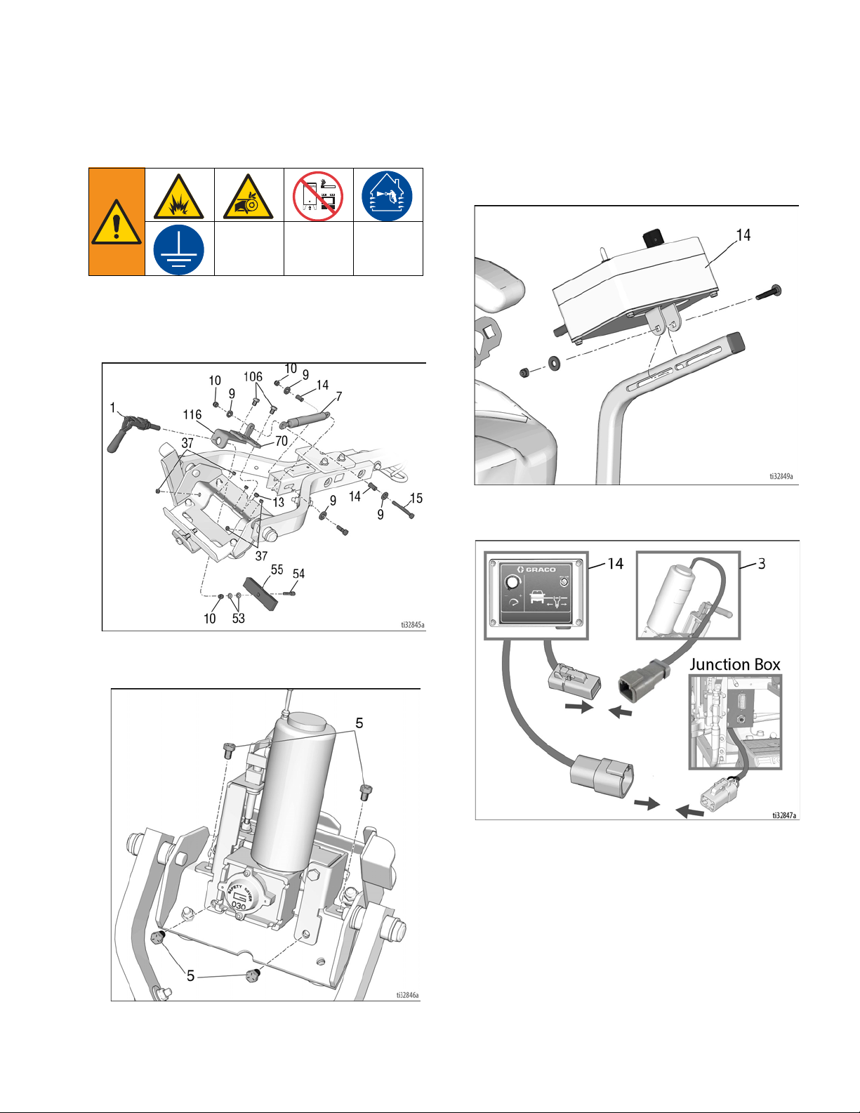
1. Remove clamp, shock assembly and set screws.
Plug threads with set screws (13). Remove gas
shock while in the fully extended, uncompressed
position (i.e. gun arm in upright, stowed position).
2. Mount steerable carriage assembly to traverse
bracket using screws (5) and thread locker (18).
3. Mount control (14) in desired location, or to control
arm of seat kit 25M716.
4. Connect wire harness from control (14) to the
plug-in at the junction box and to the motor (3).

Installation
43A5407B
5. If necessary, adjust drive roller (6) engagement by
loosening clamp (4) nut (1/8 to 1/4 turn) and then
spinning the clamp counterclockwise for more
engagement, or clockwise for less engagement.
Tighten clamp nut once proper engagement is
achieved.
6. If necessary, adjust rollers to eliminate movement in
the traverse bracket/gun arm carriage. Loosen roller
nuts just enough so that when the adjustment bolt is
turned, the rollers will move in or out as desired.
Re-tighten roller nuts to lock their position. Adjust-
ment is done correctly when the traverse
bracket/gun arm carriage slides freely and there is
no play between the rollers and the beam.
7. Use beam handle as a hard-stop to ensure carriage
cannot be driven off of the end of the beam.
NOTICE
Too much engagement between the drive roller and
the beam may cause damage to the motor and/or
drive roller. Drive roller should slip slightly if steerable
carriage movement is impeded.

Operation
3A5407B 5
Operation
1. To power the steerable carriage, the RoadPak/
RoadPak HD key must be turned to the accessory
position, or the engine must be running.
2. To engage or disengage the drive roller, toggle the
clamp handle completely to one position or to the
other. Disengaging the drive roller allows the car-
riage to slide freely.
3. Use toggle switch and speed knob together to con-
trol the direction and the speed at the same time.
Otherwise set the desired speed, and use the toggle
switch to control the direction.
4. When not in use, ensure engine key is turned to
OFF position to avoid draining the RoadPak/Road-
Pak HD battery.
NOTICE
Using the steerable carriage without the RoadPak/
RoadPak HD engine running could damage the bat-
tery due to over-discharging. Always use the steer-
able carriage with the engine running to keep the
battery charged.

Parts List
63A5407B
Parts List

Parts List
3A5407B 7
Parts List
Ref. Part Description Qty.
1 17T850 BRACKET, mount, pivot 1
2 17T851 BRACKET, motor, weldment 2
3 131377 MOTOR, gear, right angle 1
4 113304 CLAMP 1
5 131424 SCREW, cap, 3/8-24 x .50 4
6 131387 ROLLER, drive 1
7 131426 BOLT, carriage, 5/16-18 1
8 107530 SCREW, cap, sch, hex 4
9 100527 WASHER, plain 1
10 867517 SCREW, hex head, 3/8-16 x 3.5” 1
11 101566 NUT, lock, 3/8-16 1
12 131391 BEARING, flanged sleeve 2
13 131423 SCREW, set. 3/8-24 thread 2
14 17U168 BOX, switch control assembly 1
16 111040 NUT, lock, 5/16-18 1
17 124229 SCREW, set, 1/4-28 2
18 113500
THREADLOCKER, blue (not shown)
1
Ref. Part Description Qty.

All written and visual data contained in this document reflects the latest product information available at the time of publication.
Graco reserves the right to make changes at any time without notice.
For patent information, see www.graco.com/patents
Original instructions. This manual contains English. MM 3A5407
Graco Headquarters: Minneapolis
International Offices: Belgium, China, Japan, Korea
GRACO INC. AND SUBSIDIARIES • P.O. BOX 1441 • MINNEAPOLIS MN 55440-1441 • USA
Copyright 2017, Graco Inc. All Graco manufacturing locations are registered to ISO 9001.
www.graco.com
Revision B, March 2018
Table of contents
Other Graco Service Equipment manuals