Gosafe G1C User manual

1
GPS Vehicle Tracker
User Manual
(G1C)
This user manual has been specially designed to guide you through the functions and features
of your GPS vehicle tracker.

2
Content
1. Products Components and Port Definition ................................................................3
1.1 Product Introduction ................................................................................................. 3
1.2 Product Configuration List ........................................................................................ 3
1.3 Device wiring diagram ...............................................................................................4
1.4 Indicating Led Light ................................................................................................... 4
2. Specifications and functions ........................................................................................ 5
2.1 Specifications ............................................................................................................. 5
2.2 Functions ....................................................................................................................6
2.3 Setup and Operation .................................................................................................. 7
3. Common problem analysis and after-sales services ................................................... 8
3.1 Common problem analysis ........................................................................................8
3.2 Attention .................................................................................................................... 9
3.3 After-sale service ....................................................................................................... 9

3
1. Products Components and Port Definition
1.1 Product Introduction
Name
GPS Vehicle Tracker
Type
G1C
Size
86*41*12 mm
G1C Vehicle GPS Tracker is a practical and easy-to-use GPS tracker with small size and accurate
location specially designed for vehicle tracking. It combines GPS+LBS communication technology. With
EPO technology, this device can easily achieve extreme fast positioning.
1.2 Product Configuration List
No
Name
Quantity
Unit
Remark
1
G1C
1
Pcs
2
User manual; Warranty card; Certificate of approval
1
Pcs
3
Package box
1
Pcs
4
Power cable
1
pcs
4
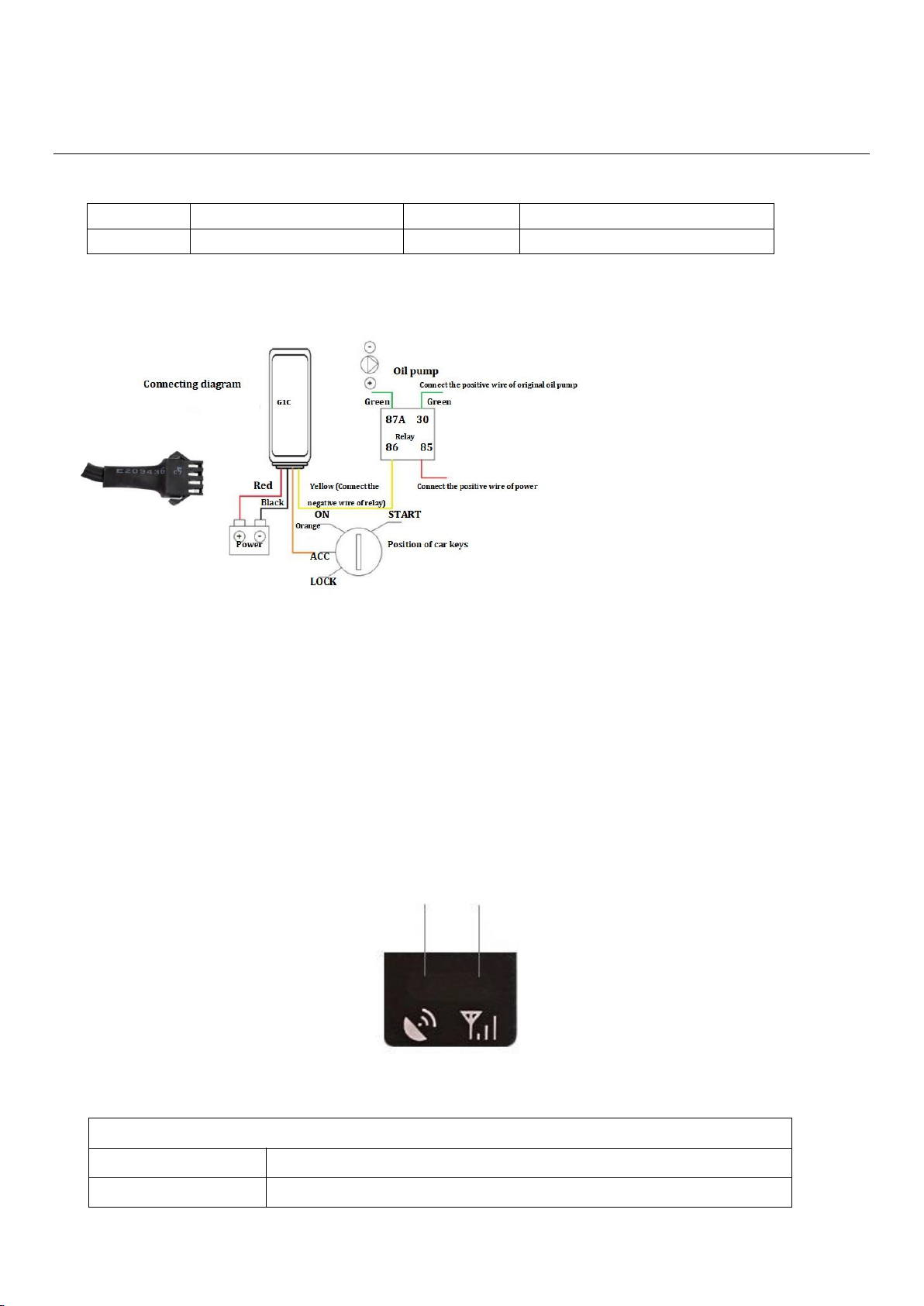
1.3 Device wiring diagram
Yellow
Relay
Orange
ACC
Black
GND
Red
Power
1.4 Indicating Led Light
GPS Indicator GSM Indicator
Yellow Red
GSM Indicator (Red)
Flash
GSM in the initialization
Slow flash
GSM signals is normal

5
Long bright
GPRS online
Not light
Not yet received the GSM signal/not insert SIM card/GSM dormancy
GPS Indicator (Yellow)
Flash
GPS signal in the search
Long bright
GPS has been positioning
Not light
GPS dormancy/not working
2. Specifications and functions
2.1 Specifications
Item
Specifications
Working Voltage
DC 6V - 90 V (wide voltage range)
Material
Plastic
Working Current
60mA @12V(static current 6~9mA )
Standby Battery
55mAH
Size
86*41*12 mm
Location Accuracy
<10 meter
Positioning way
GPS+LBS
Working Temperature
-20℃+75℃
Storage Temperature
-40℃+85℃
Communication Network
eMTC\NB-IoT\GSM
Communication ways
TCP/UDP
Weight
37.6g

6
2.2 Functions
Functions
Function details
Description
Tracking
Real time tracking
According to the stetted time update the Long
and Lat information.
Tracking
Fix distance tracking
According to the stetted distance update the
Long and Lat information.
Vehicle
status
detection
Vibration alarm
In static status, when ACC is off and
static status is lasting for at least 1
minute, if vibration is exceed the
threshold, it have alarm.
Collision alarm
When device is located, if the vibration
value exceed the threshold, it will have
alarm and upload the messages of
before and after the collision
Low power alarm
When device checking the voltage is 5-
10V and last for 20s it will have alarm
Over speed Alarm
When speed is over than the set speed,
device will send message to user.
Under voltage Alarm
When the voltage is below 5V or
disconnected to main power for 20s, it will
send a alarm location message to platform
Geo-fence
You can use the mouse to draw a circle on
the platform to set the Geo-fence, if the car
drive over that circle, the device will send
the message to the server to remind you.
Other
functions
Blind area uploading data
Storage and it will upload the data
when the signal is regular
SMS query function
Check the position of the device by sending
SMS
Inflexion upload
When the angle that vehicle turned is more
than a normal scale it will send a message to
optimize the playback
Remote upgrading
With a software

7
Harsh acceleration,brake, cornering
Harsh acceleration: if acceleration value
exceed the threshold in 1s, then generate
alarm;
Harsh brake: If acceleration value exceed
the threshold in 1s, then generate alarm;
Harsh cornering: If the angle and speed
exceed the threshold for 2S, then generate
alarm

8
2.3 Setup and Operation
a) Unit Setup
(1) Check unit
Please check whether the equipment is in good appearance & whether accessories are completed.
(2) Set In SIM Card
Please press out the SIM card slot and put SIM card in. Please not put SIM card in or out when the
equipment is connecting power. And please make sure the SIM card has data service.
(3) Setup Position
A. Waterproof: Please set the equipment in dry surroundings; keep it away from air conditioner vents
to prevent condensation water inside of the main unit.
B. Anti-Vibrate:tracker cannot install in where is long term vibrated
C. Anti-interference: tracker should stay away from car audio or intercom devices, to prevent
conducted and radiated interference.
(4) Connect GPS Antenna
A. Please notice that the GPS Antenna signal receiving side should up to sky and no metal block.
Bottom keep flat, tilt should not be more than 45°
B. Wires should be concealed;
C. Please make sure the GPS antenna is connected to the right connector and fixed tightening to avoid
vibrated.
(5) Connect to Car Main Power
Please connect the main unit to car main power according to the form before. Connect Red wire to
power “+”
---Car master positive power supply.
Black wire connects to Power “-” or grounding, but please ensures good conductivity of the grounding
place.

9
b) SMS Command for Online Tracking Setup
Command format is:
Set IP online:<SPGS*P:GSGPS*T: 120.076.068.123,7788*A:CMNET*N:13288888888*C:30>
SPGS: is Header
P: Password (default password is: GSGPS)
T: 120.076.068.123,7788 is TCP IP and Port
Q: domain name and port
A: CMNET is APN
N: 13288888888 is Device ID printed on the device.
C: Report interval , UNIT:second
c) Set upload interval
Exactly format is:
Set Upload time: <SPGS*P:GSGPS*C:030*O:600>
SPGS: is Header
P: Password (default password is: GSGPS)
C: Command word upload interval ignition ON
030: means 30Sec can change in seconds
O: Command word upload interval ignition OFF
600: means 600Sec can change in seconds
d) Command for Enable Ignition Inhibit
Enable Ignition Inhibit: <SPGS*IMB>
SPGS: Is Header
IMB: Command Word
Reply: Immobilized Successful
e) Command for Disable Ignition Inhibit
Enable Ignition Inhibit: <SPGS*RLS>
SPGS: Is Header
RLS: Command Word
Reply: Demobilized Successful
(Note: The device will immobilize if the GPS is fixed and speed is less than 20KMPH. Once the device
stopped it will release the immobilizer after 5 min and it will again immobilize if device move)

10
f) Command for Set Time zone
The device is set to China time zone by default +8. When device upload the data to server it uses default time
zone. In order to receive the data in UTC time please set the time zone to 0.
Set Time zone: zone 0:00
Reply: zone 0
3. Common problem analysis and after-sales services
3.1 Common problem analysis
Question
Reason
Solution
Online tracking offline
SIM Card not enough
credit
Charge credit
SIM Card contact
problem
Re-install SIM card
Online tracking
parameter setting
error
Reset Parameters with correct
format according to user manual
Vehicle in
underground car
parks or tunnels,
signal weak.
Go to good signal area
Cannot locate
Vehicle in
underground car
parks or tunnels
Leave that area
GPS Antenna Side is
not up to sky
Make the GPS antenna side up to
sky
Table of contents
Other Gosafe GPS manuals


