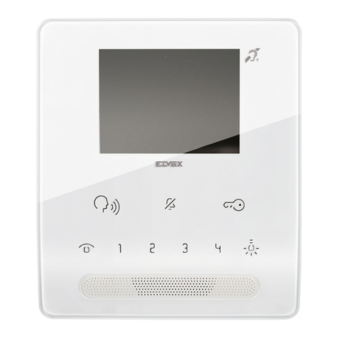
golmar SHINER-90 User manual

Golmar se reserva el derecho a cualquier modificación sin previo aviso.
Golmar reserves the right to make any modifications without prior notice.
Codificación SH-90. / SH-90 coding.
Pin 1: Activar Autoencendido
Pin 2: Monitor secundario
Pin 3: Valor 128
Pin 4: Valor 64
Pin 5: Valor 32
Pin 6: Valor 16
Pin 7: Valor 8
Pin 8: Valor 4
Pin 9: Valor 2
Pin10: Valor 1
La suma de los valores de los
pines activados (ON)
determinan el codigo del
monitor.
Pin 1: Activate auto switch-on.
Pin 2: Secondary monitor.
Pin 3: Value 128.
Pin 4: Value 64.
Pin 5: Value 32.
Pin 6: Value 16.
Pin 7: Value 8.
Pin 8: Value 4.
Pin 9: Value 2.
Pin10: Value 1.
The sum of the value of the
pins activated (ON) determines
the monitor code.
1
11
MONITOR PRINCIPAL
CON AUTOENCENDIDO
MONITOR Nº 0
MONITOR SECUNDARIO
CON AUTOENCENDIDO
MONITOR Nº0
MONITOR SECUNDARIO
SIN AUTOENCENDIDO
MONITOR Nº 0
COMUNICACIÓN
MONTANTE DE
75
++
SA2C 2C 2CA1 A1 A1
OUT IN
--
VV
+-
75
SA OUT IN
VV
75
SA OUT IN
SHINER-90SHINER-90SHINER-90
VV
Cortar la resistencia de 75ohms en
todos los monitores montados en
paralelo, excepto en el ultimo.
Cut the 75 ohm resistance in all the
monitors connected in parallel,
except the last one.
1 1 11
MONITOR PRINCIPAL
SIN AUTOENCENDIDO
MONITOR SECUNDARIO
SIN AUTOENCENDIDO
MONITOR SECUNDARIO
CON AUTOENCENDIDO
MONITOR PRINCIPAL
CON AUTOENCENDIDO
1
1 1
1 1
1 1
1
MONITOR Nº00
MONITOR Nº01 MONITOR Nº04 MONITOR Nº31 MONITOR Nº50
MONITOR Nº03 MONITOR Nº16 MONITOR Nº36
0+0+0+0+0+0+0+0 = 0
0+0+0+0+0+0+0+1 = 1 0+0+0+0+0+4+0+0 = 4 0+0+0+16+8+4+2+1 = 31 0+0+32+16+0+0+2+0 = 50
0+0+0+0+0+0+2+1 = 3 0+0+0+16+0+0+0+0 = 16 0+0+32+0+0+4+0+0 = 36
Monitor de
Vídeo
SHINER-90 TV
La comunicación por sistema
T68
Resistencia final de línea
Vout
75
Vin
8
Vout
75
Vin
12345
6
7
8
SA
2C
A1
RCSH-DOMO

Descripción.
Description.
VR7
BRILLO
VR6
FOCO
VR3
SINCRONISMO
HORIZONTAL
SWITCH DE
CODIFICACION
BUS DE
CONEXION
CONTRASTE
BRILLO
1
2
3
4
5
VR2
4
VR5
VR4
SINCRONISMO
VERTICAL
VR1
1
Instalación.
Installation.
Instalación mural.
Wall installation.
Instalación de la sonería auxiliar.
Installing additional ringer.
Instalación de la regleta de conexión.
Installing the connector.
2 31
PUENTE
SIN
1-2
2-3
MINIMO
VOLUMEN
MAXIMO
MEDIO
R1
SA
+
CN1
D1
R2+
SAV-90
3
CN2
2
1
R3
R4
VOLUMEN
MAXIMO
MEDIO
MINIMO
1-2
2-3
SIN
PUENTE
+
-
C1
C2
+
C3
T1
IC1
RCSH DOMO
SAV-90
Vout
75
Vin
12345
6
7
8
SA
2C
A1
RCSH-DOMO
Vout
75
Vin
12345
6
7
8
SA
2C
A1
RCSH-DOMO
Vout
75
Vin
12345
6
7
8
SA
2C
A1
RCSH-DOMO

Descripción de los botones.
1-.ON/OFF:
2.-SEGUNDA CÁMARA:
3.-PULSADOR AUXILIAR:
4.-VIDEO ESPÍA:
4.- AUTOENCENDIDO (sólo para instalaciones chalet):
5.-ABREPUERTAS:
5.-LLAMADA A CENTRALITA:
RECEPCIÓN DE LLAMADAS:
MONITORES EN PARALELO:
Presionar pulsador para conectar el monitor. Una vez conectado el monitor, el led rojo
permanecerá encendido. Presionar nuevamente el pulsador, para desconectar el monitor, el led
indicador de on/off permanecerá apagado. Cuando el monitor está desconectado se inhibe en su
totalidad la posibilidad de recibir llamadas.
Durante el proceso de comunicación, el autoencendido (chalet) o en la
ejecución del Vídeo Espía, se puede pulsar éste para recibir la imagen de una segunda cámara, en lugar
de recibir la de la placa.
Este pulsador se puede utilizar para la activación de otros equipos
(abrepuertas, luces,...), en cualquier instante, sin necesidad de establecer comunicación.
Durante la ejecución de la llamada, presionar el pulsador de Video Espía, para
establecer comunicación sólo de video, durante los 30" de la llamada, sin que el visitante advierta la
ejecución de la maniobra. Durante el proceso de Video Espía, se puede establecer comunicación de
audio y video, simplemente descolgando el auricular del monitor. El tiempo de comunicación, una vez
establecida, pasará a ser de 1' 30".
Descolgar el auricular del monitor, y presionar
el pulsador de autoencendido, para establecer comunicación de audio y video con la placa de calle,
preseleccionada para dicha función.
Durante el proceso de comunicación de audio y video, se presionará el pulsador de
abrepuertas para permitir el acceso del visitante a la finca, el abrepuertas permanecerá activado durante
3".
Descolgar el auricular del monitor y presionar el pulsador de
abrepuertas, el led indicador de ON/OFF parpadeará indicando la realización de la llamada. Si el led
permanece encendido nos indicará que la central está en canal ocupado. Al descolgar el auricular de la
centralita se establece comunicación de audio y video (si la centralita tiene conectada la telecámara
opcional, como elemento del sistema) con la centralita de conserjería. La comunicación permanecerá
durante 1 '30" o hasta que se cuelgue uno de los dos auriculares.
Durante la ejecución de la llamada, descolgar el auricular del monitor,
para establecer comunicación de audio y video durante 1' 30", o hasta colgar el auricular del monitor.
Para disponer de más de un monitor en una vivienda, conectar en
paralelo los monitores tal como indica el esquema de instalación. Se pueden conectar un máximo de
cinco en paralelo. Codificar uno como principal y el resto como secundarios. El monitor SH-90 viene
codificado de fabrica como monitor principal.
Push buttons description.
1-.ON/OFF:
2.- SECOND CAMERA:
3.- AUXILIARY BUTTON:
4.-VIDEO SPY:
4.- AUTO SWITCH-ON (only for Chalets installation):
5.- DOOR RELEASE:
5.- TO CALL THE EXCHANGE:
CALL RECEPTION:
MONITORS IN PARALLEL:
Press this button to connect the monitor. When connected the red led will be lit. Press again to
disconnect the monitor. The indicator light will remain off. When the monitor is disconnected, calls cannot
be received.
During communication, auto switch-on or video spy, you can press this button to
receive the image of a second camera, instead of the camera panel image.
You can use this button to activate another equipment (door-openers, lights,...)
at any time, you don't need to establish communication.
While the call is being made, press the Video Spy button to establish video communication
during the 30" that the call lasts, without the caller being aware of this action.While using the Video Spy,
audio and video communication can be established, simply by picking up the handset. Communication
time, once begun, will be 1'30".
Pick up the monitor handset and press the auto
switch-on button, to establish audio and video communication with the street door panel, preselected for
this function.
During video and audio communication, press the door-release button to allow the
visitor access tothe building.
Pick up the monitor handset and press the door release button to
establish video and audio communication with the porter's exchange (if the exchange has the optional
telecamera connected as part of the system). Communication remanis open for 1'30" or until one of the two
handsets is replaced.
While the call is being made, pick up the monitor handset, to establish audio and
video communication for 1'30", or until the handset is replaced.
To have more than one monitor in a dwelling, connect monitors in parallel.
You can connect up to five monitors. Code the monitors as principal and secondary respectively, as
indicated in the list of monitor fuctions.
Conexión del monitor a la televisión y al receptor.
Monitor connection to the television and receptor.
SHINER-90 TV
75W
Vout Vin
SA2
2
3
3
4
4
4
5
5
5
6 7 8 2C1
1
Receptor
Emisor
A1
+
-
EUROCONECTOR

Instalación para activar un segundo abrepuertas.
Installation for a second door release.
D4L-90 (*)
SHINER-90 TV
75W
SHINER-90
75W
SHINER-90
75W
CV
CV
1Vout Vin L1 L2 CV CV A
2
+
--
1 2 3
SW 4
PV-90
Vout Vin
SA2C1 2 3 4 5 6 7 8 A1
+
-
A-490/1
N R
+
-
2
0 220
PRI 1
A-490/2
SA+ T R M
SAR-90
RT M
~
0.5mm
Vin - Vout
A1, 2C,
Coaxial
Audio
Alimentación +1~2
1.0mm
1.0mm 3.0mm
RG59
Bornes 100m. 200m. 300m.
RG59 RG59
2.0mm
2
2 2
2
2
SECCIONES MINIMAS
-
0.75mm2
Vout Vin
SA2CA1
+
-
Vout Vin
SA2CA1
+
-
12
TF-103
220V
12V
RF receiver programming.
Installation and operation.
Before to connect the definitive installation, you need to validate the
emitter in the receiver.
To make this operation follow the instructions in the RF receiver kit.
There are two parts in the system Shiner-90 TV. The first part is a
standard Shiner-90 monitor and you have to connect the same installation
wires (3+coaxial), but in a different strip connector, you need the strip
conection DOMOS, not the RCSH-90 conventionnal for Shiner-90.
The second part is to see the Shiner's image in your TV set. The
connection is by EUROCONNECTOR. The installation diagram is in the
next page. You need 3 wires between strip connector to RF receiver and a
coaxial to EUROCONNECTOR.
When you receive a call from the door entry, if you push the RF emitter
the image appears automatically in the screen (if TV is switch-on). Now
there are two posibilities.
a) Press the emitter's button about 0'5
- 1 second (short touch) and 2 seconds later you'll continue watching TV.
You can recover Shiner's image if you press another time. If you don't
push in 30 seconds the image will disappear.
b) Press the emitter's button for about 3
seconds (long touch), the door will be open and Shiner-90 TV's image
continue in your screen. You can repeat this operation during 1'30". To
finish press a short touch and 2 seconds later you'll continue watching TV
channel, now is impossible to recover Shiner's image.
- If you press the Video Spy button, the image will also appear in
monitor.
- If you pick up the handset while image is in the TV screen, it will
dissapear and it will be only shown in the monitor screen.
- Sometimes you need to adjust the volume in your door entry panel
because when you open the door with the RF emitter, the monitor
stablishes communication, the handset is pick down and you could have
audio coupling.
How to use:
You don't want to open the door.
You want to open the door.
Notes:

Instalación para activar un segundo abrepuertas.
Installation for a second door release.
D4L-90 (*)
SHINER-90 TV
75W
SHINER-90
75W
SHINER-90
75W
CV
CV
1Vout Vin L1 L2 CV CV A
2
+
--
1 2 3
SW 4
PV-90
Vout Vin
SA2C1 2 3 4 5 6 7 8 A1
+
-
A-490/1
N R
+
-
2
0 220
PRI 1
A-490/2
SA+ T R M
SAR-90
RT M
~
0.5mm
Vin - Vout
A1, 2C,
Coaxial
Audio
Alimentación +1~2
1.0mm
1.0mm 3.0mm
RG59
Bornes 100m. 200m. 300m.
RG59 RG59
2.0mm
2
2 2
2
2
SECCIONES MINIMAS
-
0.75mm2
Vout Vin
SA2CA1
+
-
Vout Vin
SA2CA1
+
-
12
TF-103
220V
12V
RF receiver programming.
Installation and operation.
Before to connect the definitive installation, you need to validate the
emitter in the receiver.
To make this operation follow the instructions in the RF receiver kit.
There are two parts in the system Shiner-90 TV. The first part is a
standard Shiner-90 monitor and you have to connect the same installation
wires (3+coaxial), but in a different strip connector, you need the strip
conection DOMOS, not the RCSH-90 conventionnal for Shiner-90.
The second part is to see the Shiner's image in your TV set. The
connection is by EUROCONNECTOR. The installation diagram is in the
next page. You need 3 wires between strip connector to RF receiver and a
coaxial to EUROCONNECTOR.
When you receive a call from the door entry, if you push the RF emitter
the image appears automatically in the screen (if TV is switch-on). Now
there are two posibilities.
a) Press the emitter's button about 0'5
- 1 second (short touch) and 2 seconds later you'll continue watching TV.
You can recover Shiner's image if you press another time. If you don't
push in 30 seconds the image will disappear.
b) Press the emitter's button for about 3
seconds (long touch), the door will be open and Shiner-90 TV's image
continue in your screen. You can repeat this operation during 1'30". To
finish press a short touch and 2 seconds later you'll continue watching TV
channel, now is impossible to recover Shiner's image.
- If you press the Video Spy button, the image will also appear in
monitor.
- If you pick up the handset while image is in the TV screen, it will
dissapear and it will be only shown in the monitor screen.
- Sometimes you need to adjust the volume in your door entry panel
because when you open the door with the RF emitter, the monitor
stablishes communication, the handset is pick down and you could have
audio coupling.
How to use:
You don't want to open the door.
You want to open the door.
Notes:

Installation of one camera in each floor.
D4L-90 (*)
D4L-90 (*)
SHINER-90 TV
75W
SHINER-90
75W
SHINER-90
SHINER-90
75W
75W
CV
1Vout Vin L1 L2 CV CV A
2+
--
1 2 3
SW 4
PV-90
Vout Vin
SA2CA1 +
-
A-490/1
N R
+
-
2
0 220
PRI 1
A-490/2
TCR-05
TCR-05
+12vdc
+12vdc
+
+
-
-
SA
SA
+
+
T
T
R
R
M
M
SAR-90
SAR-90
CAMARA AUX.
CAMARA AUX.
V-1000
V-1000
R
R
T
T
M
M
Vout Vin
SA2CA1 +
-
Vout Vin
SA2CA1 +
-
Vout Vin
SA2CA1 +
-
~
0.5mm
Vin - Vout
A1, 2C,
Coaxial
Audio
Alimentación +1~2
1.0mm
1.0mm 3.0mm
RG59
Bornes 100m. 200m. 300m.
RG59 RG59
2.0mm
2
2 2
2
2
SECCIONES MINIMAS
-
0.75mm2
Instalación de una cámara por cada rellano. Instalación para activación de un equipo a 220Vac.
Installation to activate a 220Vac equipment.
D4L-90 (*)
SHINER-90 TV
75W
SHINER-90
75W
SHINER-90
75W
CV
1Vout Vin L1 L2 CV CV A
2
+
--
1 2 3
SW 4
PV-90
Vout Vin
SA2 3 4 5 6 7 8 2C1
A1
+
-
A-490/1
N R
+
-
2
0 220
PRI 1
A-490/2
SA+ T R M
SAR-90
RT M
~
0.5mm
Vin - Vout
A1, 2C,
Coaxial
Audio
Alimentación +1~2
1.0mm
1.0mm 3.0mm
RG59
Bornes 100m. 200m. 300m.
RG59 RG59
2.0mm
2
2 2
2
2
SECCIONES MINIMAS
-
0.75mm2
Vout Vin
SA2CA1
+
-
Vout Vin
SA2CA1
+
-
0 Vac
220 Vac
2 3 4 5 6 7 81
Table of contents
Other golmar Intercom System manuals

golmar
golmar m700 User manual

golmar
golmar S5110/ART 7W User manual

golmar
golmar GB2 Nexa Modular User manual

golmar
golmar Soul Art 4 User manual

golmar
golmar V2PLUS User manual

golmar
golmar Nexa User manual

golmar
golmar Stadio Plus User manual

golmar
golmar 7403/IP User manual

golmar
golmar T500EN User manual

golmar
golmar Soul kit User manual

golmar
golmar SV-372S Colour User manual

golmar
golmar G2+ User manual

golmar
golmar PCM/G+ User guide

golmar
golmar 6502/G+ User manual

golmar
golmar G2+ User manual

golmar
golmar GB2 Nexa Modular User manual

golmar
golmar ART 4TH/G+ User manual

golmar
golmar Stadio Plus T4000ML User manual

golmar
golmar Rock Series User manual

golmar
golmar GB2A User manual