Goldstar DH3010B User manual

Dehumidifier
SERVICE MANUAL
MODEL: DH3010B(DHA3012DL)
DH4010B(DHA4012DL)
DH5010B(DHA5012DL)
CAUTION
- BEFORE SERVICING THE UNIT,
READ THE SAFETY PRECAUTIONS IN THIS MANUAL.
- ONLY FOR AUTHORIZED SERVICE.
http://biz.LGservice.com
http://www.LGservice.com/techsup.html

—2—
1. PREFACE
1.1 SAFETY PRECAUTIONS...........................................................................................................................3
1.2 FEATURES.................................................................................................................................................3
1.3 DIMENSIONS.............................................................................................................................................3
1.4 SPECIFICATIONS......................................................................................................................................4
1.5 CONTROL ..................................................................................................................................................5
1.6 HOW TO OPERATE DEHUMIDIFIER........................................................................................................5
1.6.1 HOW DOES THE DEHUMIDIFIER WORK? .....................................................................................5
1.6.2 LOCATION FOR THE DEHUMIDIFIER.............................................................................................5
1.6.3 MICRO SWITCH................................................................................................................................6
1.6.4 AUTO DEFROST...............................................................................................................................6
1.6.5 HUMIDISTAT.....................................................................................................................................6
1.6.6 DRIER ...............................................................................................................................................6
2. CIRCUIT DIAGRAM............................................................................................................................7
3.
DISASSEMBLY INSTRUCTIONS
3.1 MECHANICAL PARTS .............................................................................................................................10
3.1.1 BUCKET AND AIR FILTER.............................................................................................................10
3.1.2 FRONT GRILLE...............................................................................................................................10
3.1.3 CABINET AND CONTROL BOX .....................................................................................................10
3.2 CONTROL PARTS ..................................................................................................................................11
3.2.1 ROTARY SWITCH, HUMIDISTAT AND NEON LAMP....................................................................11
3.2.2 CAPACITOR ...................................................................................................................................11
3.2.3 DEFROST CONTROL.....................................................................................................................11
3.2.4 THERMOSTAT CONTROL .............................................................................................................11
3.2.5 MICRO SWITCH ASSY...................................................................................................................11
3.2.6 POWER CORD ASSY.....................................................................................................................11
3.2.7 FAN AND MOTOR...........................................................................................................................12
3.2.8 SHROUD AND BARRIER................................................................................................................12
3.3 REFRIGERATING CYCLE .......................................................................................................................13
3.3.1 CONDENSER, EVAPORATOR AND CAPILLARY TUBE
(HEAT EXCHANGE ASSEMBLY)...................................................................................................13
3.3.2 P.T.C. OR OVERLOAD PROTECTOR (O.L.P.) FOR RECIPROCATING COMPRESSOR ...........14
3.3.3 ROTARY COMPRESSOR ..............................................................................................................14
3.4 HOW TO REPLACE REFRIGERATION SYSTEM...................................................................................15
4. TROUBLESHOOTING GUIDE...................................................................................................17
5. EXPLODED VIEW - INTRODUCTION..................................................................................20
6. REPLACEMENT PARTS LIST...................................................................................................23
CONTENTS

—3—
1. PREFACE
This Service Manual provides various service information, containing the mechanical and electrical parts etc.
This dehumidifier was manufactured and assembled under the strict quality control system.
The refrigerant is charged at the factory. Be sure to read the safety precaution prior to servicing the unit.
1.1 SAFETY PRECAUTIONS
• Disconnect power supply before servicing or replacing any electrical or non-electrical component.
• Do not cut off the grounding prong or alter the plug in any manner at any circumstances.
1.2 FEATURES
• Quiet
• High efficiency
• Adjustable humidistat
• Automatic defrost
• Automatic shut-off
• Bucket-full indicator light
• Easy roll casters
• Removable & large capacity bucket.
• Washable air filter
• 2 fan speeds
• Drain hose connection.
1.3 DIMENSIONS (mm/in)
320 (12 9/16) 340 (13 3/8)
445 (17 1/2)
530 (20 3/16)

—4—
1.4 SPECIFICATIONS
CAPACITY (Pint/Day) 30 40 50
POWER SUPPLY (Phase, V, Hz) 1ø, 115V, 60Hz
REFRIGERANT R134a R22
REFRIGERANT CHARGE, oz(g) 4.76(135) 5.11(145) 7.05(200)
CONTROL, DEFROST
THERMOSTAT
HUMIDISTAT CONTROL RANGE : 20% ~ 80% RH
NORMAL SETTING : 42 ± 5% RH
COMPRESSOR MODEL NO. LX86HACG QA075CH QA082CH
TYPE P220MC
TIME
AMPERE
7A
VOLTAGE 300V
•OVERLOAD PROTECTOR FOR COMPRESSOR
•INTERNAL PROTECTOR(FUSE) FOR MOTOR
CAPACITOR - 25µF, 270VAC
SWITCH, ROTARY 6A/125VAC, 12A/250VAC
MOTOR ASSEMBLY, SINGLE
Shaded pole motor, 65W/1A, Thermal cutoff : 266°F/130°C
SWITCH ASSEMBLY, MICRO 16A/125VAC, 8A/250VAC
WITHOUT BUCKET
320 x 530 x 340 (12 9/16 x 20 13/16 x 13 3/8)
WITH BUCKET 320 x 530 x 445 (12 9/16 x 20 13/16 x 17 1/2)
NET WEIGHT, kg(lbs) 21.5(47) 17.2(38) 17.7(39)
MODELS
ITEMS
P.T.C.
ASSEMBLY
MAXIMUM
WORKING TIME: 0.2 ~ 0.7 sec.
RETURN TIME: 60 sec. –
OUTSIDE
DIMENSIONS
W x H x D, mm(in)
PROTECTOR
※※NOTE : Specifications are subject to minor change without notice for further improvement.
OPEN : 32°F(0°C)
CLOSE : 52.6°F(13°C)
–
OPEN : 32°F(0°C)
CLOSE : 53.6°F(13°C)
+ 3
–3
+ 2
–3
+ 3
–3
+ 2
–3
OPEN : 28.4°F(-2°C ±2)
CLOSE : 55.4°F(13°C ±2)
OPEN : 26.6°F(-3°C ±2)
CLOSE : 55.4°F(13°C ±2)
OPEN : 28.4°F(-2°C ±2)
CLOSE : 55.4°F(13°C ±2)
DH3010B
(DHA3012D*) DH4010B
(DHA4012D*) DH5010B
(DHA5012D*)

1.6.1 HOW DOES THE DEHUMIDIFIER WORK?
Moist, humid air is drawn over a cold refrigerated
dehumidifying coil. Moisture in the air condenses on this
coil and drains into a bucket (or through the bucket into a
hose and drain).
Dry, clean air is drawn over the condenser where it is
actually heated several degrees and discharged out the
front grille into the room.
It is normal for the surrounding air to become slightly
warmer as the dehumidifier operates.
This warming effect further reduces the relative humidity
of the surrounding air.
1.6.2 LOCATION FOR THE DEHUMIDIFIER
Allow at least 12 inches of space on all sides of the
unit for good air circulation.
■The dehumidifier must be operated in an enclosed
area to be most effective.
■Close all doors, windows and other outside
openings to the room.
Place the dehumidifier in a location that does not
restrict air flow into the rear coil or out the front grille.
A dehumidifier operating in a basement will have little
or no effect in drying an adjacent enclosed storage
area, such as a closet, unless there is adequate
circulation of air in and out of the area.
Humidity Control
•
When you first use the dehumidifier, turn the humidity
control to 5or 6. If you still have moisture, turn the
humidity control to a higher setting.
MAX is the highest setting.
•When excess moisture and dampness odors are gone,
adjust the control to a lower setting. Use the
dehumidifier as long as excess moisture is present.
Fan Speed
•
The fan control adjusts the fan speed.
Set the fan control to HIGH for maximum moisture
removal. When the humidity has been reduced and
quiet operation is preferred, set the fan control to LOW.
—5—
HighLow
8
Humidity Control
Fan Speed
Auto
Shut-Off Off
1
2
3
456
7
9
Max.
Dry
Air Out Humid
Air In
Fan
Compressor
Side View
Bucket
Condenser Evaporator
Motor
Drain
Connection
12"
Air In
Air Out
12"
Figure 1
Figure 2
1.6 HOW TO OPERATE DEHUMIDIFIER
1.5 CONTROL
•
Glows when the bucket is ready to be emptied, or when
the bucket is removed or not replaced in the proper
position.
•The Water Level Control Switch shuts off the
dehumidifier when the bucket is full, or when the bucket
is removed or not replaced in the proper position.
Auto Shut-Off

1.6.5 HUMIDISTAT
Humidistat controls constant relative humidity in the room
automatically.
When the relative humidity in the room increases to the
selected level, the dehumidifier starts automatically. And the
relative humidity drops to the selected level, the
dehumidifier stops automatically.
When the first using the dehumidifier, it is recommended,
for the first three or four days, to operate the unit with the
humidistat control set to MAX. At this setting, the unit will
run continuously.
When the sweating has stopped and the dampness odors
have gone, it is preferable to select the humidistat position
that will best suit local conditions.
The relative humidity range it can control is from 20 % to
80%. (See Figure 3)
NOTE: The relative humidity at the number is the
approximate value.
1.6.6 DRIER (For some models)
Dryer is used to prevent capillary blockage from moisture in
the refrigerant system and H/E, condenser and evaporator.
Also, dryer is used to remove corrosion of the components.
NOTE: When dryer is replaced, proper injection to
capillary is needed. On opening the dryer, it
should be welded instantly. The oxidization of
dryer inside and all tubes inside after welding
can be prevented.
—6—
42% R.H 40%
7(30%)
6(35%)4(50%)
3(60%)
2(70%)
1(80%)
5(42%)
8(25%)
9(20%)
Max.Off DEAD DIAL
Dryer
Figure 4
Figure 3
1.6.3 MICRO SWITCH
The micro switch assembly, which is located on the barrier of inside unit, automatically shuts off the dehumidifier when the
bucket is full (note, the Auto Shut Off lights, to indicate bucket must be emptied). The bucket replaces in its place, the unit again
turns itself on.
1.6.4 AUTO DEFROST
When frost builds up on the cooling coils, the compressor will cycle off until the frost disappears. The fan continues to run.
NOTE: This unit is designed to be operated at temperatures above 65°F(18°C). If the dehumidifier is operated in low
temperature conditions, the temperature and humidity conditions of room are low, some frost can be formed in
its evaporator coil and the unit will be operated ON/OFF repeatedly. In this case, please check on your room
temperature condition and stop the unit.

—7—
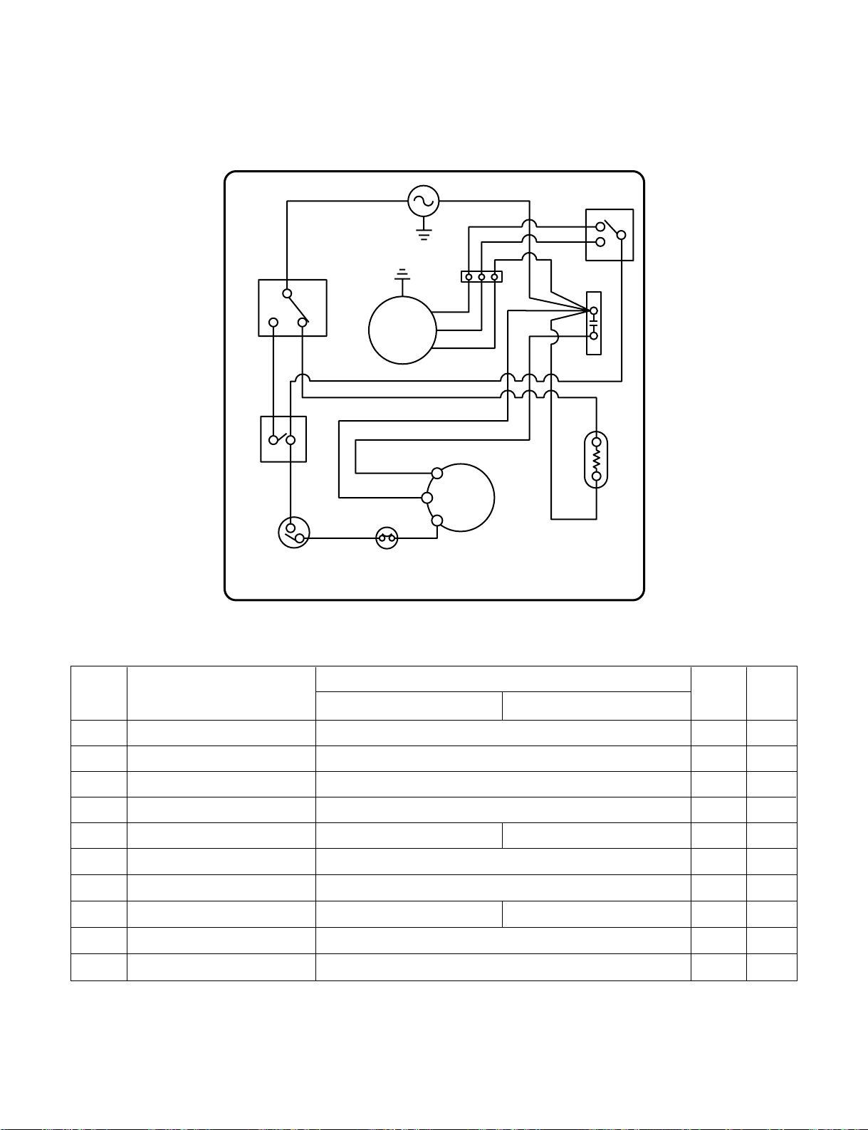
2. CIRCUIT DIAGRAM
• MODEL : DH3010B/DHA3012DL
LAMP,
NEON
TERMINAL
BLOCK
WIRING DIAGRAM 3854A20015H
CONTROL,
DEFROST O.L.P.
SWITCH,
ROTARY
C
BR YL
BR
BR BR
6
41
1
HUMIDISTAT
2BK
BK
M
S
5
63
4
C
COMP.
BK WH
OR(COM)
RD(LO)
BK(HI)
OR
RD(L)
BK(HI)
GR/YL
BL
N.C
N.O MOTOR
SWITCH,
LAMP
GR/YL
Q'TY
PER SET
1
1
1
1
1
1
1
1
1
1
1
RE-
MARKS
S, A
S
S
S
S
S
S
S
S, A
S
S
LOCATION
NO.
1
2
3
4
5
6
7
8
9
10
11
DESCRIPTION
POWER CORD ASSEMBLY
SWITCH, ROTARY
MOTOR ASSEMBLY, SINGLE
P.T.C. ASSEMBLY
COMPRESSOR
O.L.P.
LAMP, NEON
CONTROL, DEFROST
HUMIDISTAT
SWITCH ASSEMBLY, MICRO
TERMINAL BLOCK
DH3010B
6411A20001Q
6600A20001A
4681A20040A
6748C-0003A
2521C-A8605
6750C-0002S
6912A30001F
6614A30001H
5216A20001A
6600A30003C
6640A40001A
PART NO.
※S: SERVICE PARTS A: ALTERNATE PARTS N: NOT SERVICE PARTS
—8—
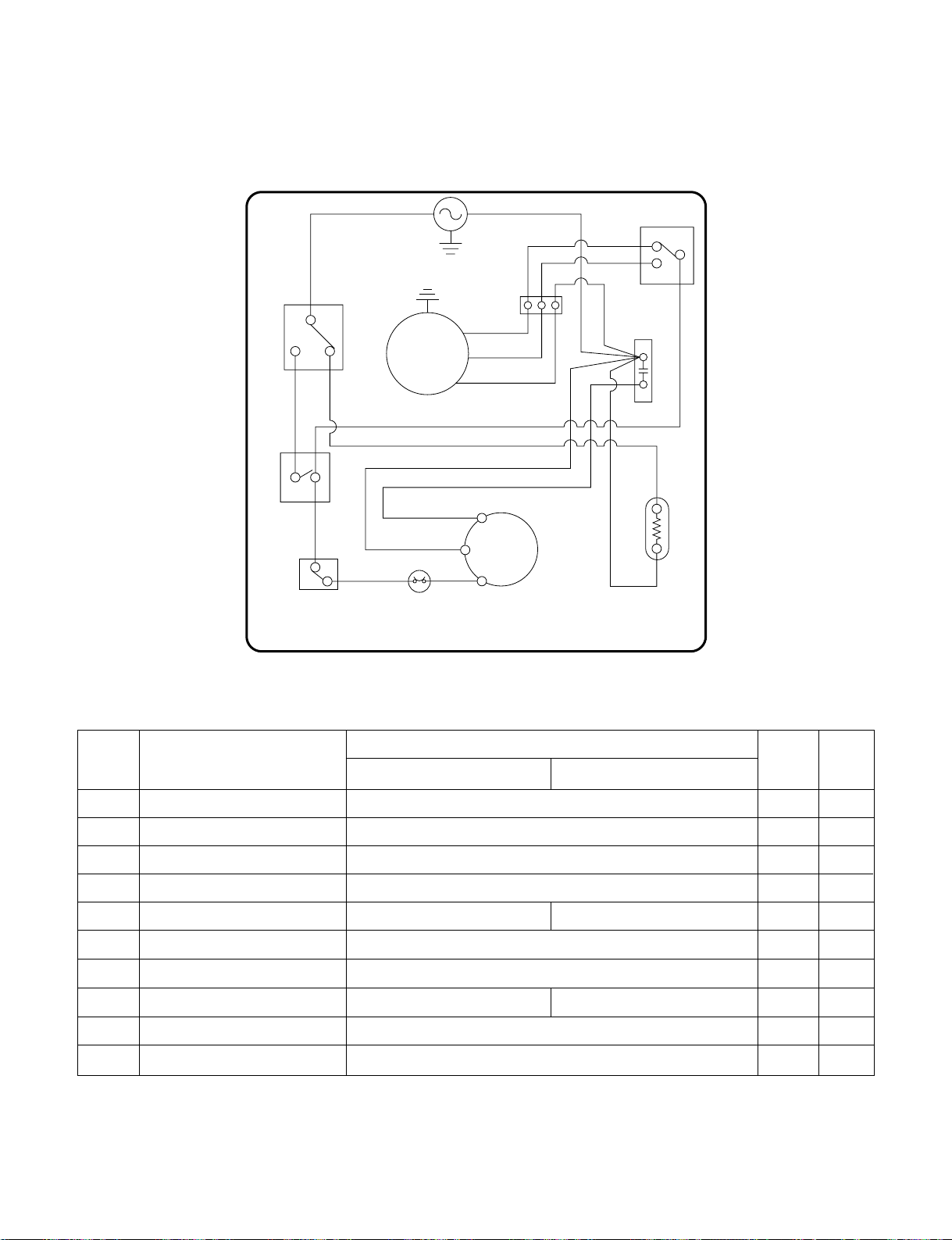
• MODEL : DH4010B/DHA4012DL, DH5010B/DHA5012DL(DEFROST CONTROL TYPE)
LAMP,
NEON
WIRING DIAGRAM
3854A20015G
CONTROL,
DEFROST O.L.P.
SWITCH,
ROTARY
C
BR YL
BR
BR BR
6
41
1
HUMIDISTAT
2
BK
RD
BK
RD
BK
S
R
C
COMP.
BK WH
OR
OR
C
H
RD(LO)
BK(HI)
RD
BK
GR/YL
GR/YL
BL
N.C
N.O MOTOR
SWITCH,
LAMP
CAPACITOR
Q'TY
PER SET
1
1
1
1
1
1
1
1
1
1
RE-
MARKS
S, A
S
S
S
S
S
S
S
S, A
S
LOCATION
NO.
1
2
3
4
5
6
7
8
9
10
DESCRIPTION
POWER CORD ASSEMBLY
SWITCH, ROTARY
MOTOR ASSEMBLY SINGLE
CAPACITOR
COMPRESSOR (ROTARY)
O.L.P.
LAMP, NEON
CONTROL, DEFROST
HUMIDISTAT
SWITCH ASSEMBLY, MICRO
DH4010B DH5010B
6411A20001Q
6600A20001A
4681A20040A
0CZZA20001Q
2520UABC2FA 5416AR2179J
6750U-L039A
6912A30001F
–6614A30001F
5216A20001A
6600A30003C
PART NO.
※S: SERVICE PARTS A: ALTERNATE PARTS N: NOT SERVICE PARTS
—9—
• MODEL : DH4010B/DHA4012DL, DH5010B/DHA5012DL(THERMOSTAT CONTROL TYPE)
BK WH SWITCH,
ROTARY
SWITCH,
LAMP
BK C
H
BR
BK
LAMP,
NEON
THERMOSTAT O.L.P
WIRING DIAGRAM 3854A20015M
BL
BK
RD
BK
BR
BR
RD
COMP
R
C
S
RD
OR
OR
4
6
1
GR/YL
GR/YL
MOTOR
C
N.O
N.C
12
BR YL
CAPACITOR
HUMIDISTAT
BK(HI)
RD(LOW)
LC
Q'TY
PER SET
1
1
1
1
1
1
1
1
1
1
RE-
MARKS
S, A
S
S
S
S
S
S
S
S, A
S
LOCATION
NO.
1
2
3
4
5
6
7
8
9
10
DESCRIPTION
POWER CORD ASSEMBLY
SWITCH, ROTARY
MOTOR ASSEMBLY SINGLE
CAPACITOR
COMPRESSOR (ROTARY)
O.L.P.
LAMP, NEON
THERMOSTAT
HUMIDISTAT
SWITCH ASSEMBLY, MICRO
DH4010B DH5010B
6411A20001Q
6600A20001A
4681A20040A
0CZZA20001Q
2520UABC2FA 5416AR2179J
6750U-L039A
6912A30001F
2H01127K 2H01127J
5216A20001A
6600A30003C
PART NO.
※S: SERVICE PARTS A: ALTERNATE PARTS N: NOT SERVICE PARTS
3.1 MECHANICAL PARTS
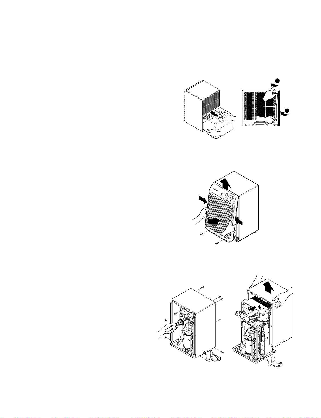
3.1.1 BUCKET AND AIR FILTER
1. Disconnect the power supply.
2. Turn the Humidity Control off.
3. Remove the bucket. (See Figure 5)
4. Flex the filter at the lower right corner and take it
off. (See Figure 5)
3.1.2 FRONT GRILLE
1. Remove 2 screws which fasten the front grille.
2. By pushing the both sides of front grille, pull the
front grille forward and upward. (See Figure 6)
3.1.3.
CABINET AND CONTROL BOX
1. Remove the Bucket, the Air filter and Front grille
according to the procedure above.
2. Remove 3 screws that fasten Control box.
(See Figure 7)
3. Remove 9 screws on all sides of the cabinet.
4. Lift the Cabinet from the base.(See Figure 8)
5. Remove a screw fasten the earth wire on the front
of control box.
6. Unhook control box from two hooks on the shroud.
(See Figure 8)
—10—
3. DISASSEMBLY INSTRUCTIONS
1
2
Push
Push
Figure 5
Figure 6
Figure 7 Figure 8
This manual suits for next models
5
Table of contents
Other Goldstar Dehumidifier manuals

Goldstar
Goldstar DH305Y7 User manual

Goldstar
Goldstar DH300E User manual

Goldstar
Goldstar GD300S User manual

Goldstar
Goldstar DH30 User manual

Goldstar
Goldstar DH300M User manual

Goldstar
Goldstar DH30 User manual

Goldstar
Goldstar DH404E User manual

Goldstar
Goldstar DH504ELY6 User manual

Goldstar
Goldstar DH300EY6 User manual

Goldstar
Goldstar DH300E User manual

Goldstar
Goldstar DH65EL User manual

Goldstar
Goldstar DH30E, DH40E, DH50E, DH50EL, D User manual

Goldstar
Goldstar DH2510A User manual

Goldstar
Goldstar DH300E User manual

Goldstar
Goldstar DH3010A User manual

Goldstar
Goldstar DH30 User manual

Goldstar
Goldstar DH300E User manual

Goldstar
Goldstar DH305 User manual


