Golden Companion User manual
Companion
Service Guide
This Service Guide contains:
Troubleshooting
Replacement Instructions

WWW.GOLDENTECH.COM [email protected] PAGE - 2
Contact Information
Golden Technologies
401 Bridge Street
Old Forge, PA 18518
Toll-free: 800-624-6374
Fax: 800-628-5165
Lift Chair/Bed Tech: x502
Mobility Tech: x501
VA Tech: x505
Email: [email protected]

WWW.GOLDENTECH.COM [email protected] PAGE - 3
Table of Contents
ABOUT THE COMPANION SERVICE GUIDE .................................................................................................... 4
Companion Components ............................................................................................................................................................... 4
SCENARIO 1: TURN THE KEY TO THE ON POSITION AND NO POWER ................................................ 13
SCENARIO 2: BATTERIES WON'T CHARGE .................................................................................................. 14
FLASH CODES ........................................................................................................................................................ 15
FLASH CODE #1 – Batteries Low (Scooter may drive slowly.) ................................................................................................ 15
FLASH CODE #2 – Batteries Low (Scooter will not operate.) .................................................................................................. 15
FLASH CODE #3 - High Battery Voltage................................................................................................................................... 15
FLASH CODE #4 - Current Limit Timeout ................................................................................................................................ 15
FLASH CODE #5 - Brake Fault .................................................................................................................................................. 16
FLASH CODE #6 - Paddle Fault (out of neutral) ....................................................................................................................... 17
FLASH CODE #7 - Paddle Fault/Speed Control Fault (voltage error) ....................................................................................... 17
FLASH CODE #8 - Motor Voltage Fault (Open) ........................................................................................................................ 18
FLASH CODE #9 - Controller Fault ........................................................................................................................................... 19
COMPANION REPLACEMENT INSTRUCTIONS ............................................................................................ 20
Motor/Brake Assembly Replacement .......................................................................................................................................... 20
Motor Brush Replacement ........................................................................................................................................................... 21
Drivewheel Replacement ............................................................................................................................................................. 21
Battery Replacement ................................................................................................................................................................... 21
Throttle Pot Replacement ............................................................................................................................................................ 22
Key Switch Replacement ............................................................................................................................................................ 22
Control Panel Fuse Replacement................................................................................................................................................. 22
Circuit Breaker Replacement ...................................................................................................................................................... 23
Controller Replacement ............................................................................................................................................................... 23
Charger Harness Fuse Replacement ............................................................................................................................................ 24
Main Harness Replacement (340) ............................................................................................................................................... 24
APPENDIX A - HOW TO USE A VOLTMETER.................................................................................................. 26
APPENDIX B - HOW TO USE AN OHM METER .............................................................................................. 27
APPENDIX C - WIRING DIAGRAM .................................................................................................................... 28

WWW.GOLDENTECH.COM [email protected] PAGE - 4
About the Companion Service Guide
This service guide provides you with the information necessary to troubleshoot the Golden Technologies Com-
panion (GC-240, GC-340, and GC-440) equipped with the R-Series Controller. The troubleshooting scenarios in this
manual consist of procedures that enable you to systematically trace and correct faults in the system. Appendices A and
B include instructions on how to use a multimeter to measure voltage and continuity. Appendix C includes a copy of
figure 13 that may be printed separately.
Before troubleshooting, check the following:
• Make sure that the circuit breaker is reset.
• Visually check terminals for corrosion. Check wires for missing insulation.
• Make sure that the batteries are fully charged and are in good working order. When possible, keep sets of
known good batteries of various ratings in your shop at all times. The Companion uses two (2) 35AH (U1)
batteries. Problems that surface during troubleshooting are often due to the fact that the batteries are not fully
charged or cannot hold their charge.
• Make sure that the electrical connections are secure. Unplug the connectors and make sure all of the pins
are seated properly. Push the pins back into the connector housing if necessary. Make sure that the battery
terminals are tight.
NOTE: If you get to a point during troubleshooting where you cannot continue, call tech support at
800-624-6374.
COMPANION COMPONENTS
The Companion is a battery-operated scooter controlled by a Dynamics R-Series controller. The R-Series
controller monitors the system and displays flash codes when it detects a fault in the system. The Companion was
designed to operate within a range of between 18 – 24 volts (V) of direct current (DC).
The Companion control system is made up of the following components.
NOTE: The number after the component refers to the components position on figure 13 on page 10.
• Circuit Breaker (1) SE06E602
• 12V/U-1 Batteries (2 and 3) MBE-BATTU1
• Battery Harnesses (4 and 5) (4) SE06A612 Battery Cable Left (5) SE06A614 Battery Cable Right
• Power Harnesses (6 and 7) (6 & 7 sold as set) SE06E602
• Dynamics R-Series Controller (8) 3051600170
• Main Harness (9) All models: SE08A601ASB
• Rear Intermediate Motor Harness (10) SE06E604
• Front Intermediate Motor Harness (11) SE06E606
• Motor/Brake Assembly (12) MBX-CMBAR-2
• Charger Harness (13) SE06A610
• Throttle Pot (14) SE06E603
• Speed Pot (15) N/A
• Key Switch (16) MBH-C40-KSWITCH
• Headlight LED (17) SE06E605
• Taillights (18) SE06E502 Tail Light Assembly
• Tail Light Lenses SE06A505 (Left) SE06A504 (Right)
• Harness, Tail Light w/bulb SE06A620 ***24-volt/5-watt bulb
• Front Intermediate Light Harness (19) SE06E608
• Rear Intermediate Light Harness (20) SE06E607
• Off-Board Battery Charger MBE-MRC4
WWW.GOLDENTECH.COM [email protected] PAGE - 5
NOTE: The number after each component refers to the
components position in figure 13 on page 10.
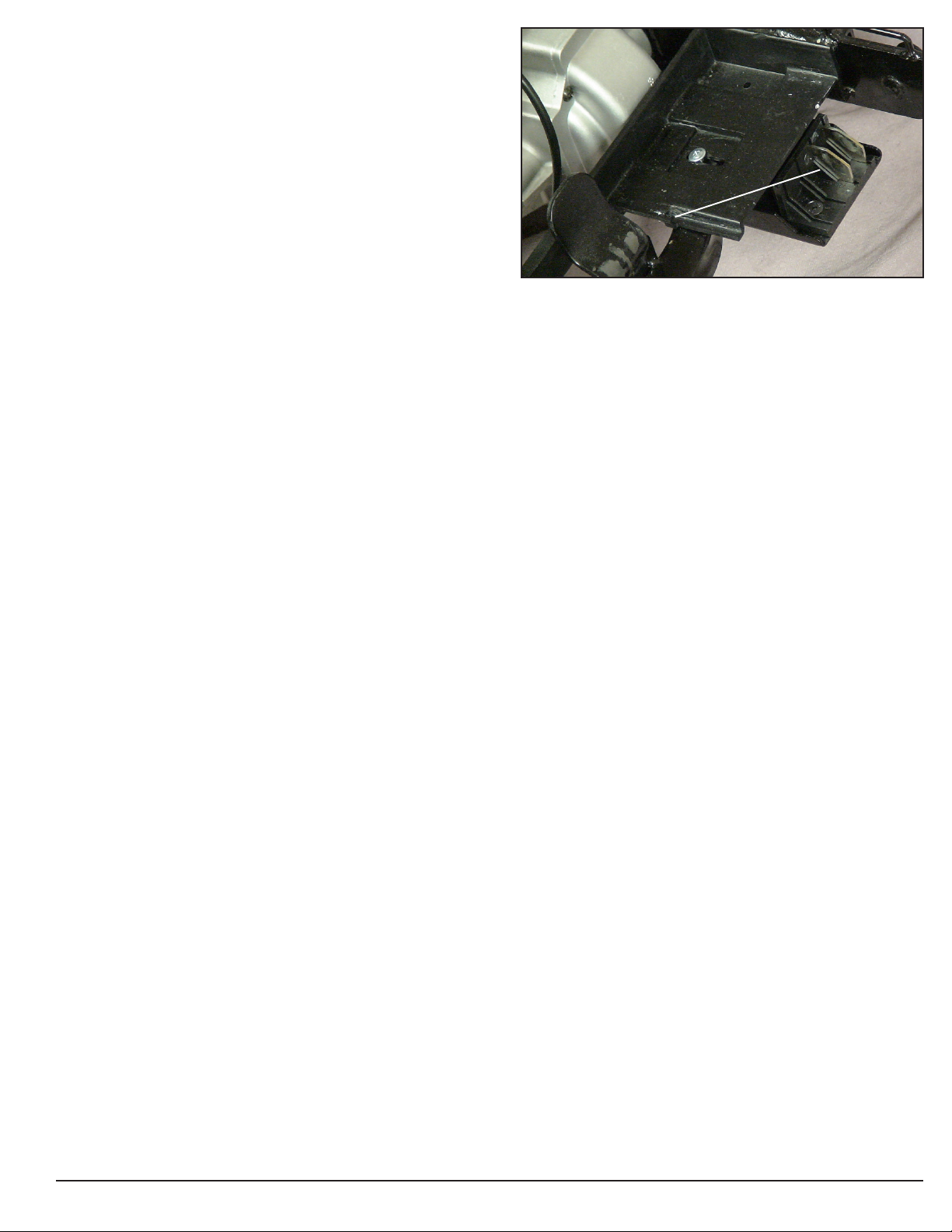
Component: 50 amp Circuit Breaker (1)
Location: Mounted on the front frame under the seat. See
figure 1.
Function: Protects battery circuit from current overload. When
the current draw exceeds the breaker rating, the circuit breaker
will open.
Connections: The circuit breaker is connected to the power
harnesses (6b and 7b.)
Failure Signs: Opens repeatedly. May indicate failed circuit
breaker or short in the wiring. May also open if the motors are
overloaded (from excessive weight, short in system, etc.)
Test: Measure the resistance across the circuit breaker.
Expected reading: Less than 10 ohms.
Serviceable: Circuit breaker must be replaced with exact
current rating.
Component: 12VDC/U-1 Batteries (2 and 3)
Location: Connected in series under the rear shroud. See
figure 2.
Function: Supply 24VDC to the motor and/or accessories
(12VDC x 2)
Connections: Positive (+) and negative (-) terminals connect to
the Battery Harnesses (4 and 5).
Failure Signs: Batteries drain quickly. Scooter runs slowly or
not at all. Batteries will not charge, but charger is working
properly. Flash Code #1 or #2.
Tests: Fully charge the batteries first and load test. Make sure
charging system is working. See Battery Charging Test.
Expected Readings: 12 - 14VDC each when fully charged.
Serviceable: Replace batteries as necessary.
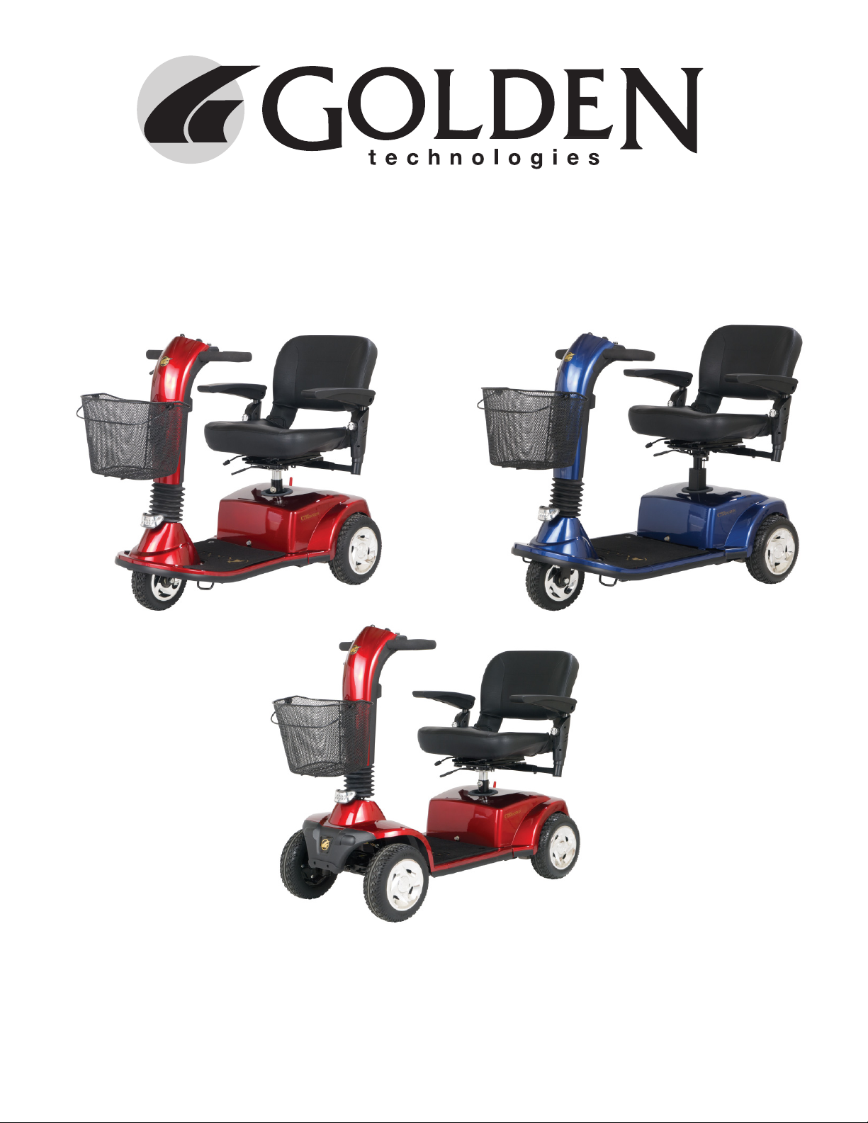
Component: Battery Harnesses (4 and 5)
Location: Connected to the positive (+) and negative (-)
terminal on the batteries. See figure 2.
Function: Connects the batteries to the Power Harnesses (6
and 7)
Connections: 4a and 4b connect to the neg (-) and pos (+)
terminals on Battery 2. 5a and 5b connect to the neg (-) and pos
(+) terminals on Battery 3. 4c and 5c connect to the Power
Harnesses.
Failure Signs: Corroded wires may cause the batteries not to
work properly. Make sure connector pins are seated properly.
Tests: Check the inline fuse on the battery harness. Test the
harnesses and the 125A fuse for continuity.
Expected Readings: Less than 10 ohms.
Serviceable: Replace 125A fuse and/or harnesses as necessary.
Figure 1. Circuit Breaker
Figure 2. Battery and Battery Harness
Figure 3. Power Harness
POWER HARNESS
WWW.GOLDENTECH.COM [email protected] PAGE - 6
Component: Power Harnesses (6 and 7)
Location: Mounted to the front frame - under the rear shroud. See
figure 3.
Function: Connects the Batteries Harnesses (4 and 5) to the Circuit
Breaker (1) and the Controller (8).
Connections: 6a and 7a connect to the Battery Harnesses (4 and 5).
6b and 7b connect to the Circuit Breaker (1). 6c and 7c connect to the
Controller (8).
Failure Signs: Batteries will not charge, but charger is working
properly. No power to the controller.
Tests: Test harnesses for continuity. Check connectors. Make sure the
contacts are not corroded and are seated properly.
Expected Readings: Continuity (less than 10 ohms.)
Serviceable: Replace as necessary.
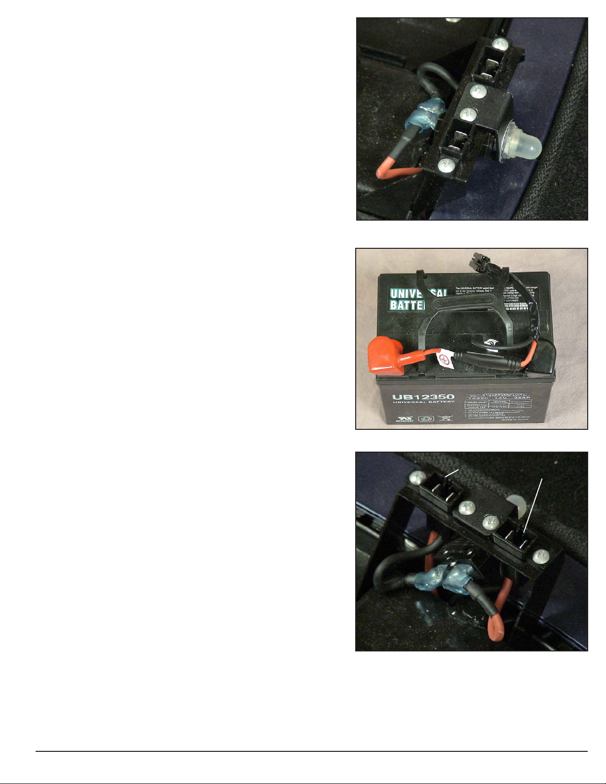
Component: Controller (8)
Location: Under the front frame. See figure 4.
Function: Controls and monitors the system. It displays faults
through the status light when something in the system is out of range.
Connections: Main Harness (9a), Front Intermediate Motor Harness
(11b, 11c, and 11d), Power Harnesses (6c and 7c).
Failure Signs: Flash Code #9. No power to the Control Panel or the
Motor.
Tests: Test for voltage to motor and to the Control Panel.
Expected readings: Battery voltage.
Serviceable: Replace as necessary.
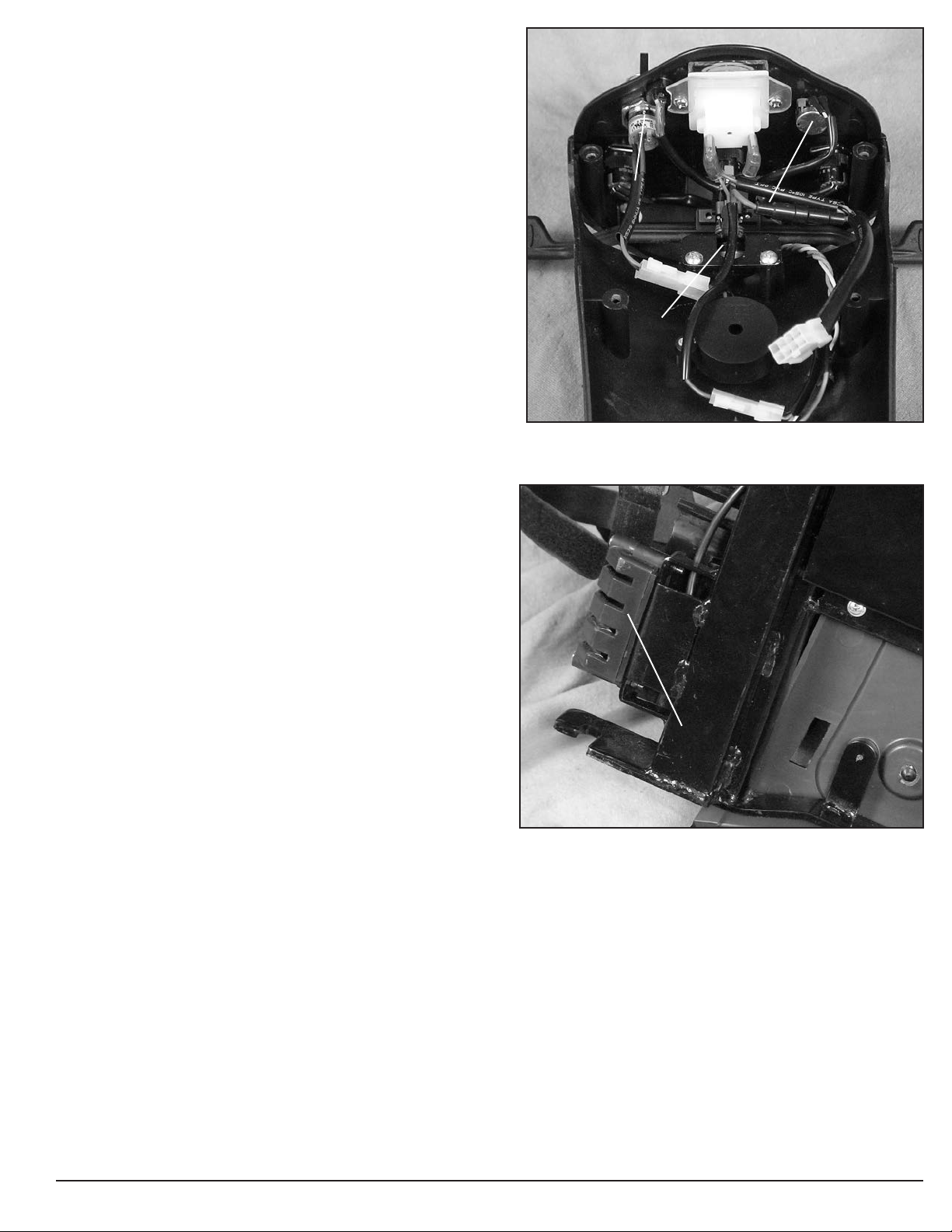
Component: Main Harness (9)
Location: Inside the tiller (shown in figure 5) and under front frame.
Function: Provides connectivity for the tiller components and the
controller.
Connections: Connects to the Control Panel, the Headlight LEDs, the
Throttle Pot (14a), and the Charger Harness (13b), in the tiller. Con-
nects to the Controller (8a), the Front Intermediate Light Harness, and
the Optional Power Seat under the front frame.
Failure Signs: Batteries will not charge. Scooter will not run.
Tests: Test for voltage and continuity. Check connectors. Make sure
the pins are not corroded and are seated properly.
Expected readings: Battery voltage. Continuity (less than 10 ohms.)
Serviceable: Replace as necessary.
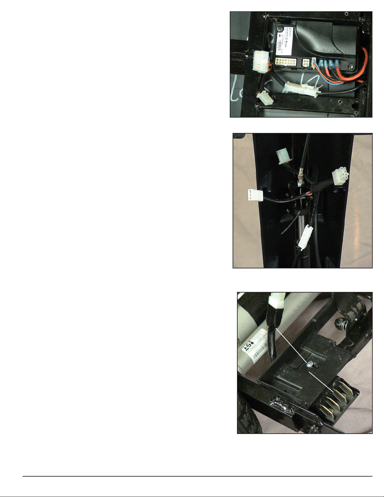
Component: Rear Intermediate Motor Harness (10)
Location: On the right side of the rear frame. See figure 6.
Function: Provides connectivity for Motor/Brake Assembly (12) and
the Front Intermediate Motor Harness (11.)
Connections: Connects to the Front Intermediate Motor Harness
(11a) and the Motor/Brake Assembly (12a).
Failure Signs: Scooter will run slowly or not at all.
Tests: Test for voltage and continuity. Check connectors. Make sure
the pins are not corroded and are seated properly.
Expected readings: Continuity (less than 10 ohms.)
Serviceable: Replace as necessary.
Figure 4. Controller
Figure 5. Main Harness (Tiller Side)
Figure 6. Rear Intermediate Motor Harness
REAR INTERMEDIATE MOTOR HARNESS
WWW.GOLDENTECH.COM [email protected] PAGE - 7
Component: Front Intermediate Motor Harness (11)
Location: On the right side of the front frame. See figure 7. FRONT INTERMEDIATE MOTOR HARNESS
Function: Provides connectivity for Rear Intermediate
Motor Harness (10) and the Controller (8).
Connections: Connects to the Rear Intermediate Motor
Harness (10a) and the Controller (8b, 8c, and 8d.)
Failure Signs: Scooter will run slowly or not at all.
Tests: Test for voltage and continuity. Check connectors.
Make sure the contacts are not corroded. (See figure 16 on
page 16 for quarter test.)
Expected readings: Continuity (less than 10 ohms.)
Serviceable: Replace as necessary.
Component: Motor/Brake Assembly (12)
Location: Rear section of scooter on the transaxle. See
figure 8.
Function: Drives the scooter.
Connections: Motor and Brakes (12a) to Rear Intermediate
Motor Harness (10b.)
Failure Signs: Scooter runs slowly or not at all.
Tests: Test for internal resistance in motor. Test motor
wires for continuity. See Flash Code #5 and #8.
Expected readings: Internal motor resistance is less than
50 ohms but not shorted. Brake resistance is less than 80
ohms but not shorted.
Serviceable: Replace the motor/brake assembly or motor
brushes.
Component: Charger Harness (13)
Location: Inside the tiller.
Function: Provides connectivity for the battery charger and
the main harness (9).
Connections: Connects to the battery charger at (13a) and
to the main harness (9d.)
Failure Signs: Batteries will not charge.
Tests: Test for voltage and continuity. Check connectors.
Make sure the pins are not corroded and are seated prop-
erly. Check fuse.
Expected readings: Continuity (less than 10 ohms.)
Serviceable: Replace the 10A fuse or harness as necessary.
Component: Throttle Pot (14)
Location: Control Panel. See figure 10.
Function: The throttle potentiometer (pot) uses variable
resistance to control speed and direction of travel by
varying voltage.
Connections: Main Harness (9c.)
Failure Signs: Flash Codes #6 and #7
Tests: Test resistance across the pins 1 and 3 and on 14a.
Expected readings: Depends on direction of deflection.
Serviceable: Replace as necessary.
Figure 7. Front Intermediate Motor Harness
Figure 8. Motor/Brake Assembly
Figure 9. Charger Harness
CHARGER HARNESS
MOTOR/BRAKE ASSEMBLY
WWW.GOLDENTECH.COM [email protected] PAGE - 8
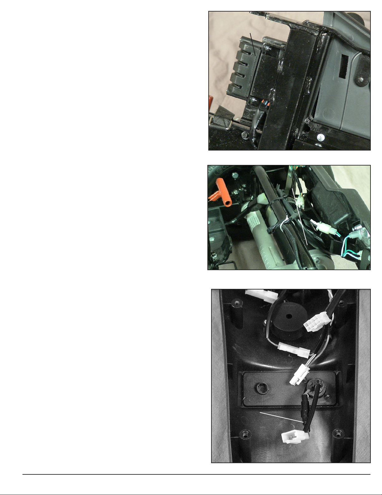
Component: Speed Pot (15)
Location: Control Panel. See figure 10.
Function: The speed potentiometer (pot) uses variable
resistance to control the top speed of the scooter.
Connections: Control Panel Harness
Failure Signs: Flash Code #7
Tests: Call Tech Support
Expected readings: Depends on speed pot position.
Serviceable: Replace the Control Panel.
Component: Key Switch (16)
Location: Control Panel. See figure 10.
Function: Completes the circuit to provide power to the motor.
Connections: Control Panel Harness
Failure Signs: No power when the key is in the ON position.
Tests: Continuity when the key is in the “ON” position.
Make sure the connector pins are seated properly.
Expected readings: Less than 10 ohms.
Serviceable: Replace as necessary.
Component: Headlight LEDS (17)
Location: Tiller.
Function: Provides lighting.
Connections: Main Harness
Failure Signs: No lights.
Tests: Check voltage to headlights with power switch on.
Expected readings: Battery voltage.
Serviceable: Replace as necessary.
Component: Taillights (18)
Location: Rear frame.
Function: Provides lighting.
Connections: Rear Intermediate Light Harness
Failure Signs: No lights.
Tests: Check voltage to tail lights with power switch on.
Expected readings: Battery voltage. Check bulbs for
discoloration or broken filament.
Serviceable: Replace with 24-volt/5-watt bulbs as necessary.
Component: Front Intermediate Light Harness (19)
Location: On the left side of the front frame. See figure 11.
Function: Provides connectivity for the Rear Intermediate
Light Harness and the Main Harness.
Connections: Connects to the Rear Intermediate Light
Harness and the Main Harness.
Failure Signs: Rear lights will not go on.
Tests: Test for voltage and continuity. Check connectors.
Make sure the pins are not corroded and are seated properly.
Expected readings: Less than 10 ohms.
Serviceable: Replace as necessary.
Figure 10. Control Panel (underside)
Figure 11. Front Intermediate Light Harness
THROTTLE POT
SPEED POT
KEY SWITCH
FRONT INTERMEDIATE LIGHT HARNESS
WWW.GOLDENTECH.COM [email protected] PAGE - 9
Component: Rear Intermediate Light Harness(20)
Location: On the left side of the rear frame.
Function: Provides connectivity for the Front Intermedi-
ate Light Harness and the Rear Lights.
Connections: Connects to the Front Intermediate Light
Harness and the Rear Lights.
Failure Signs: Rear lights will not go on.
Tests: Test for voltage and continuity. Check connectors.
Make sure the pins are not corroded and are seated properly.
Expected readings: Continuity (less than 10 ohms.)
Serviceable: Replace as necessary.
Component: Off-Board Battery Charger
Location: Stored inside a pouch on the seatback.
Function: Recharges batteries.
Connections: Connects to the charger port on the tiller
(13a.) Charger harness is located inside tiller. Connects
the charger to the main harness.
Failure Signs: Charger power LED does not go on.
Batteries will not charge.
Tests: Charger tests vary. Some chargers may be tested by
measuring positive and negative leads on the charger
connector. Other chargers need to see battery voltage
before charging.
Expected reading: Varies with charger. See charger test.
Test charger harness and 10A/250V fuse for continuity.
Serviceable: Replace if necessary
NOTE: Some Off-Board Battery Chargers may have a
switch that enables them to be used with either 110 VAC
or 230 VAC. This switch is typically located on the end
of the charger. Some may also have a removable 10A/
250V glass fuse.
Figure 12. Rear Intermediate Motor Harness
REAR INTERMEDIATE LIGHT HARNESS
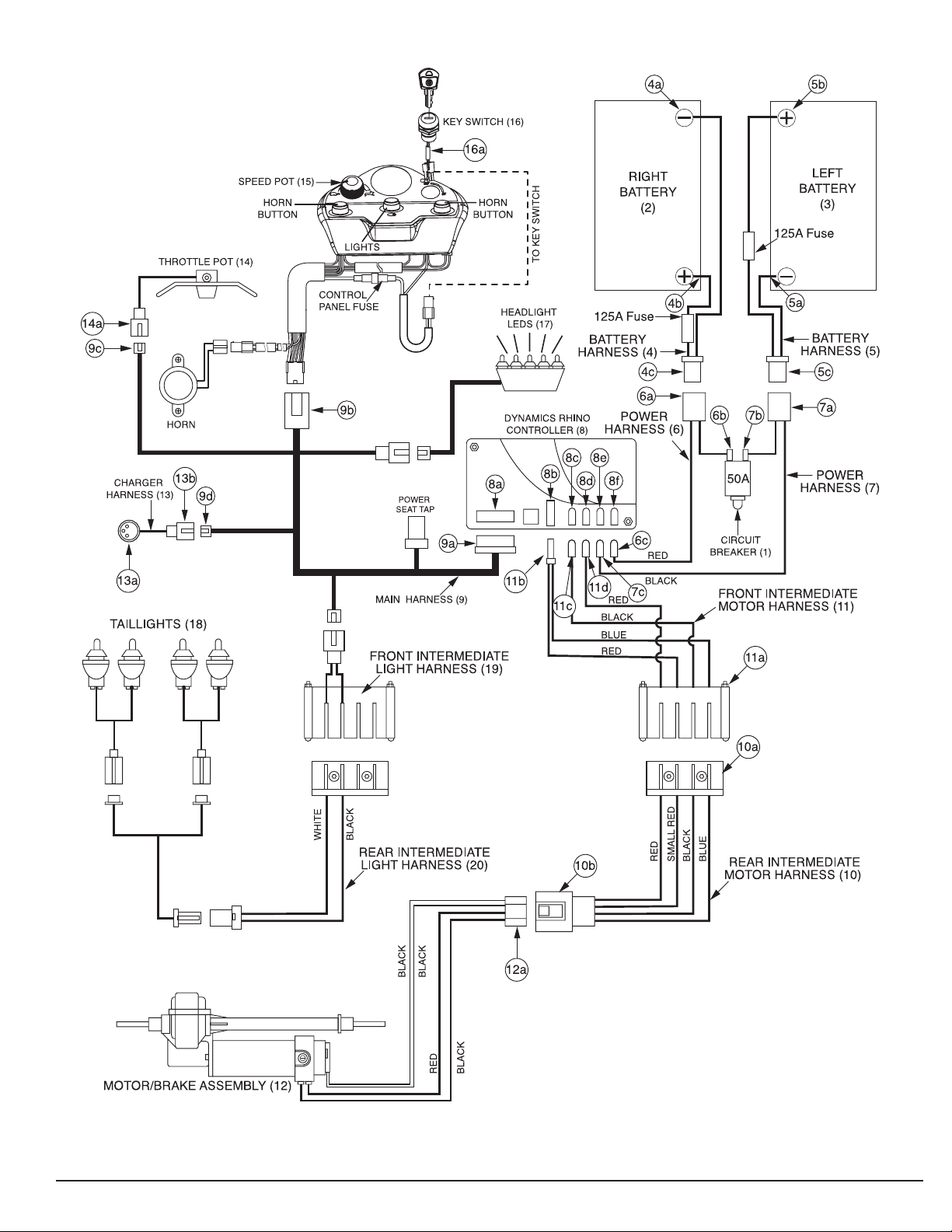
Table of contents
Other Golden Scooter manuals

Golden
Golden GC240 User manual

Golden
Golden Buzzaround Lite User manual

Golden
Golden Buzzaround XL Series User manual

Golden
Golden Buzzaround Carry On User manual

Golden
Golden Buzzaround Extreme GB118EX User manual

Golden
Golden Avenger GA541 User manual

Golden
Golden LiteRider GL111 User manual

Golden
Golden LiteRider GL140 User manual

Golden
Golden Buzzaround XL GB117 User manual

Golden
Golden Companion II User manual


