Global Specialties DSC-5300 User manual

I
Content
Brief Introduction .......................................................................................................I
Chapter 1 Accidence ................................................................................................1
1.1 Accidence of Panel and Display Information .................................................................2
1.2 Function Checking..........................................................................................................5
1.3 Probe ...................................................................................................................7
1.3.1 Probe Safety ..........................................................................................................7
1.3.2 Probe Attenuation Setting....................................................................................7
1.3.3 Probe Compensation............................................................................................8
Chapter 2 Functions Instruction and Operation........................................................9
2.1 Menu and Control Button .............................................................................................10
2.2 Connector......................................................................................................................12
2.3 Auto Setup ....................................................................................................................12
2.4 Default Setup ................................................................................................................14
2.5 Universal Knob .............................................................................................................15
2.6 Vertical System.............................................................................................................15
2.6.1 CH1, CH2 Channel .............................................................................................16
2.6.2 Using Vertical “Position” Knob and “Volt/div” Knob .......................................21
2.6.3 Math Functions ....................................................................................................22
2.6.4 Using Ref..............................................................................................................28
2.7 Horizontal System.........................................................................................................30
2.7.1 Horizontal Control Knob.....................................................................................31
2.7.2 Window Zone.......................................................................................................32
2.8 Trigger System..............................................................................................................33
2.8.1 Signal Source.......................................................................................................34
2.8.2 Trigger Type.........................................................................................................34
2.8.3 Coupling................................................................................................................47
2.8.4 Position .................................................................................................................48
2.8.5 Slope & Level.......................................................................................................48
2.8.6 Trigger Holdoff ........................................................................................49
2.9 Acquiring Signals System.............................................................................................49
2.10 Display System ...........................................................................................................55
2.10.1 X-Y Format.........................................................................................................59
2.11 Measure System..........................................................................................................59
2.11.1 Scale Measurement..........................................................................................60
2.11.2 Cursor Measurement........................................................................................60
2.11.3 Auto Measurement ...........................................................................................66
2.12 Storage System ...........................................................................................................72
2.13 Utility System .............................................................................................................85
2.13.1 System Status ...................................................................................................88
2.13.2 Language ...........................................................................................................88
2.13.3 Self Calibration ..................................................................................................89
2.13.4 Self Test ................................................................................................................90
2.13.5 Updating the System Software .......................................................................92
2.13.6 Pass/Fail.............................................................................................................92
2.13.7 Waveform Record.............................................................................................96
2.13.8 Recorder.............................................................................................................99
2.13.9 Remote Control ...............................................................................................102
Test Equipment Depot - 800.517.8431 - 99 Washington Street Melrose, MA 02176
TestEquipmentDepot.com

II
2.14 Online Help Function................................................................................................109
Chapter 3 Prompting Messages and Troubleshooting .........................................110
3.1 Prompting Messages:..................................................................................................110
3.2 Troubleshooting ..........................................................................................................112
Chapter 4 Service and Support ............................................................................114
4.1 Maintain Summary .....................................................................................................114
4.2 Contact GLOBAL SPECIALTIES .............................................................................114
Appendix A: Default Setup ...................................................................................115
Appendix B: Daily Maintain and Cleaning ............................................................117

Chapter 1 Overview
DSC-5300 Series Digital Oscilloscope is mini-type and portable bench type instruments,
which could be used for measuring as the GND voltage.
This Chapter shows you how to operate following tasks:
•Accidence of panel and Display information
•Simple checking of functions
•Matching probes attenuation coefficient
•Probe compensation

2
1.1 Overview of Panel and Display Information
1.1.1 Front Panel
It is important for you to understand the DSO’s front panel before operating it. The
following contents are the brief introduction for the front panel function, which is useful
to be familiar with the operation of the DSC-5300 Digital Storage Oscilloscope in short
time.
The oscilloscopes provides an easy-to-use front panel to convenience users to operate
them, the panel contains knobs and buttons. There is a list of five ashen buttons as menu
operational buttons on the right of display screen. You can set different options of the
current menu in virtue of them. Other buttons are function buttons; you can enter
different function menus or obtain given function application in virtue of them.
Picture 1.1-1 DSC-5300 Front Panel
Test Equipment Depot - 800.517.8431 - 99 Washington Street Melrose, MA 02176
TestEquipmentDepot.com

3
No.
Description
No.
Description
1
On/Off Button
10
Probe Compensator
2
Menu On/Off,
Menu Softkeys
11
Horizontal Controls
3
Intensity Adjustment
12
External Trigger Input
4
Control Keys
13
Vertical Controls
5
Default Setup Key
14
Input Channels
6
Help Key
15
Print Key
7
Run Control Panel
16
Front USB Connector
8
Autoset Key
17
Display
9
Trigger Control Panel
1.1.2 Back and Side Connections
The following images show back and side panel connection locations.
Picture 1.1-2 DSC-5300 Back and Side panel

4
1. Handle
2. AC Power Input Terminal
3. USB Device Connector
4. Pass/Fail Output Connector
5. LAN Port
6. Lock Hole
1.1.3 User display interface
Picture 1.1-3
1.Product Logo
Global Specialties is the registered trademark of our company.
2. Trigger status
Armed. The oscilloscope is acquiring pre-trigger data. All triggers are ignored in this
state.
Ready. All pre-trigger data has been acquired and the oscilloscope is ready to accept
a trigger.
Trig’d. The oscilloscope has seen a trigger and is acquiring the posttrigger data.
Stop. The oscilloscope has stopped acquiring waveform data.
Auto. The oscilloscope is in auto mode and is acquiring waveforms in the absence of

5
triggers.
Scan. The oscilloscope is acquiring and displaying waveform data continuously in scan
mode.
3. USB Host connected mark.
4.Waveform memory
Show the position of the current waveform in the memory of the oscillsocpe.
5.Trigger position.
Turn the HORIZONTAL POSITION knob to adjust the trigger position of the
waveform.
6.Show the LAN port.
Indicates the LAN port is connected.
ndicates the LAN port is disconnected.
7.Show the Channel symbol.
8.Readout shows trigger signal frequency..
9.Readout shows the trigger level value and trigger type..
10.Readout shows the trigger delay of waveform.
11.Readout shows the main time base setting.
12. Icon shows the channel setting.
13. Icon shows the channel offset position.
14. Icon shows the trigger level position
1.2 Function Checking
When you check whether or not the oscilloscope could work smoothly, please operate
as following:
1. Power On the oscilloscope.
Press “DEFAULT SETUP” to show the result of the self check. The probe default
attenuation is 1X.
Test Equipment Depot - 800.517.8431 - 99 Washington Street Melrose, MA 02176
TestEquipmentDepot.com

6
Picture 1.2- 1
2. Set the switch to 1X on the probe and connect the probe to channel 1 on the
oscilloscope. To do this, align the slot in the probe connector with the key on the CH 1
BNC, push to connect, and twist to the right to lock the probe in place. Connect the probe
tip and reference lead to the PROBE COMP connectors
Picture 1.2-2
3Press “AUTO” to show the 1 KHz frequency and about 3V peak-peak square wave
in couple seconds
Picture 1.2-3

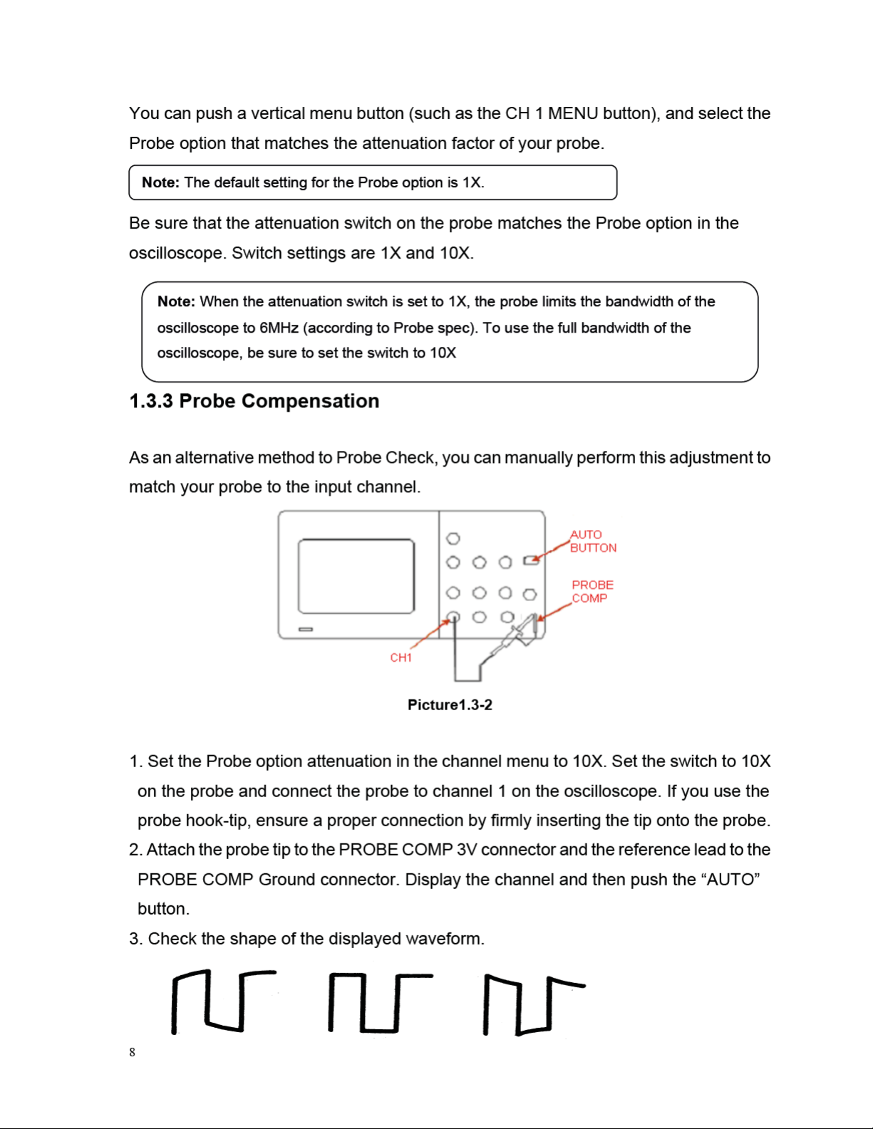
Table of contents
Other Global Specialties Test Equipment manuals


