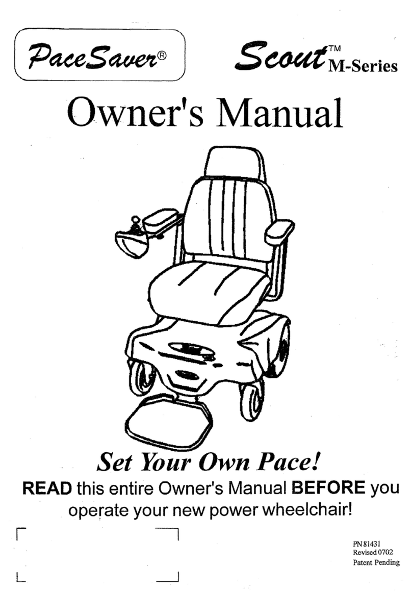
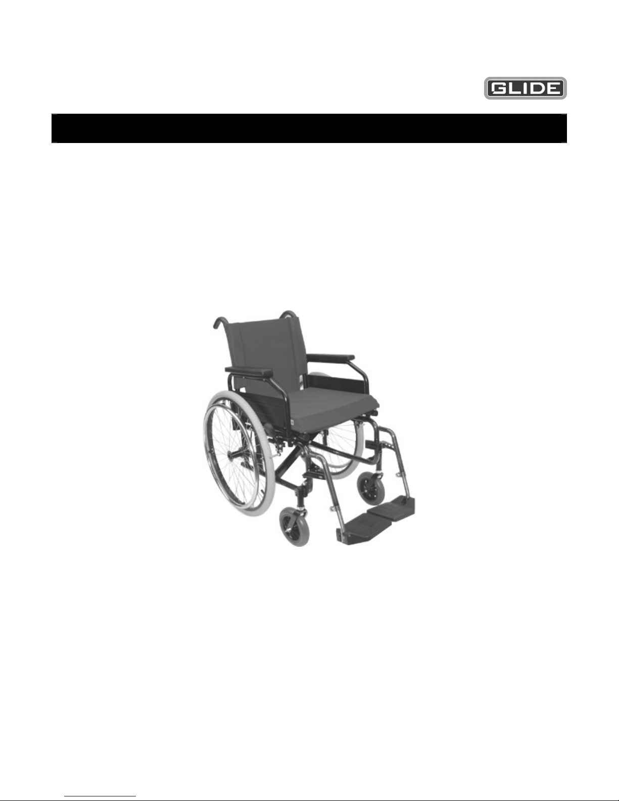
Glide G2 Series User manual

1
Rehabilitation Products
G2 Series Owner / User Manual
For your safety and comfort read carefully and understand all of the features prior to using
your new manual wheelchair.
Maximum recommended user weight 150kg

2
Table of Contents
Section Description Page
1 Introduction 3
2 Getting Acquainted With Your New Chair 4
3 Backrest and Seat Upholstery 4
4 Armrest 5
5 Footplates 5
6 Forks and Castors 6
7 Castor Alignment 6
8 Wheels 7
9 Brakes 8
10 Rear Wheel Position 8 - 9
11 Folding and Opening the Wheelchair 9
12 Cross Brace 9
13 Tyres / Castor Tyres 10
14 Operation of Wheelchair 11 – 12
15 Transporting your Chair 12 – 13
16 Options 14
17 Servicing 15
18 Warranty 15 - 17
3
Section 1
Introduction
Thank you for choosing the Glide G2 Manual Wheelchair.
An Australia designed and manufactured product which complies with AS 3695 and has a
manufacturers recommended user weight of 150kg.
With proper care and operation, your G2 chair will provide years of trouble free use.
Please take the time to familiarize yourself with the functions and features of your chair by
reading this owner / user manual. If you have any queries about the functions of the chair you
can call Glide Rehabilitation Products or your nearest Glide Rehabilitation Products dealer.
Glide Rehabilitation Products
+61 8 9345 3400
4
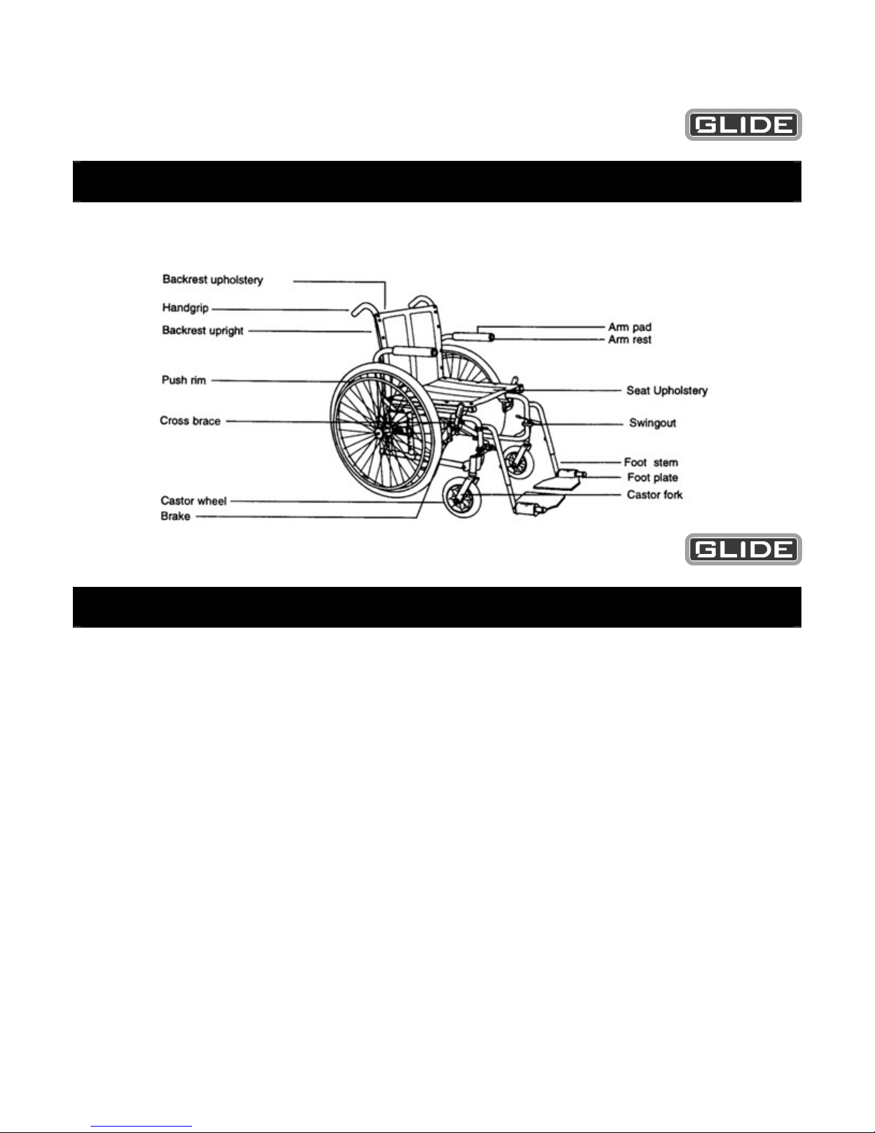
Section 2
Getting acquainted with your new chair
Section 3
Upholstery
With proper care your upholstery should give years of trouble free service. It is very important
to read the following:
•Regular (weekly) cleaning of back and seat upholstery is very important to remove
body oils which can cause hardening of the vinyl.
To clean, wipe with a clean cloth or sponge, which has been moistened in warm soapy
water, and then dry with a soft, clean cloth. The use of mild non-abrasive pure soap is
recommended. Stubborn grime may require gentle scrubbing with a soft brush.
Warning
•Never use furniture polishes, abrasive cleaners or steel wool.
Regular use of cleaners containing hydrocarbons or similar additives may cause
damage to the vinyl and harden the surface.
•Always replace broken upholstery screws immediately to avoid possible tearing.
•Stretched, torn or split upholstery must be replaced for safety reasons.
5
Section 4
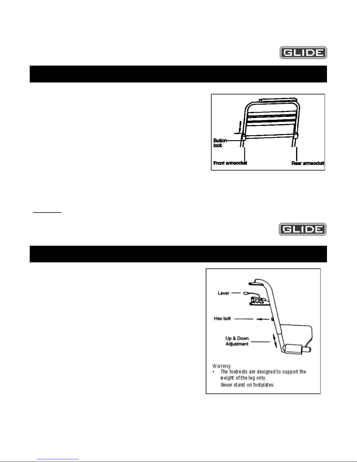
Armrest
To remove:
•Push button and hold in on front arm socket.
•Using the other hand lift armrest upwards.
Note: Wheelchairs may be supplied without button
locks.
To install:
•Replace armrest into front and rear arm sockets,
push button in and armrest down
simultaneously.
•Ensure armrest is secure and button has popped
out.
Warning
•Never lift wheelchair by armrest as damage may
occur.
Section 5
Footrest
To remove:
•Push lever inwards to unlock and swing
outwards.
•Lift upwards to remove.
To install:
•Insert footrest back on the two locating pins
and swing inwards for automatic locking.
To adjust footplates:
•Remove hexagonal bolt.
•Move up or down. Line up the nearest hole for
the desired height.
•Replace hexagonal bolt and tighten.
Note: Your wheelchair may be fitted with
swing
away armrests. Simply lift up full arm and
swing to one side or lift up and remove
completely.
6
Section 6
Fork and Castors
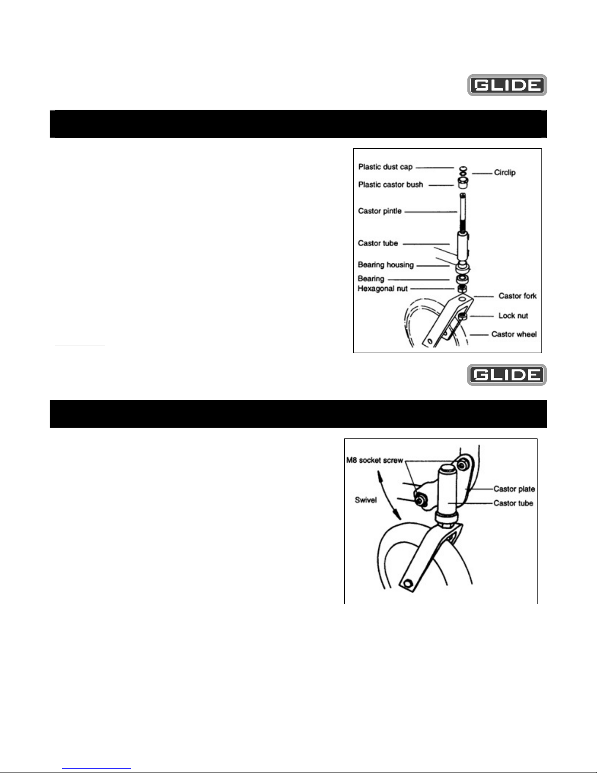
•Assembly
•Press bearing housing into bottom of castor
tube.
•Press castor bush into top of castor tube.
•Slide castor pintle through bearing bearing
housing and castor bush.
•Place circlip on castor pintle.
•Slide bearing on pintle and locate in bearing
housing.
•Screw hex-nut until there is 1mm of up and down
pintle movement.
•Place castor fork in position and tighten locknut.
Important
Once tightened ensure 1mm of up and down movement
and castor turns freely.
Section 7
Castor Alignment
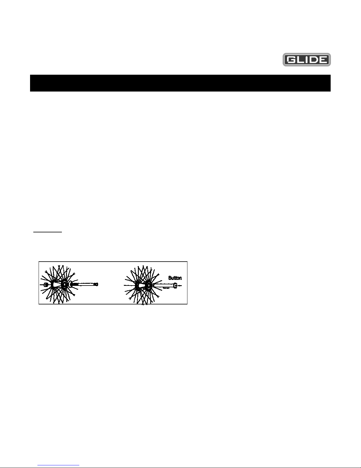
•Incorrect castor alignment will render the
wheelchair difficult to steer and propel.
Alignment should be checked when rear
wheels have been repositioned or if castors
have had a heavy knock (e.g. hitting a kerb).
Adjustment
•To adjust, place the wheelchair on level ground
and loosen both M8 socket screws until castor
plate can swivel. Using a square, set castor
tube at 90 degrees to the ground and lock in
position.
•When both castors are set, ensure all screws
are tight before use.
7
Section 8
Wheels
The large wheels are fitted with sealed bearings and should last many years without
replacement.
Large wheels (fixed)
•To remove large wheels unscrew locknut and using a large screwdriver unscrew the
axle and remove when free.
•Installation in the reverse procedure.
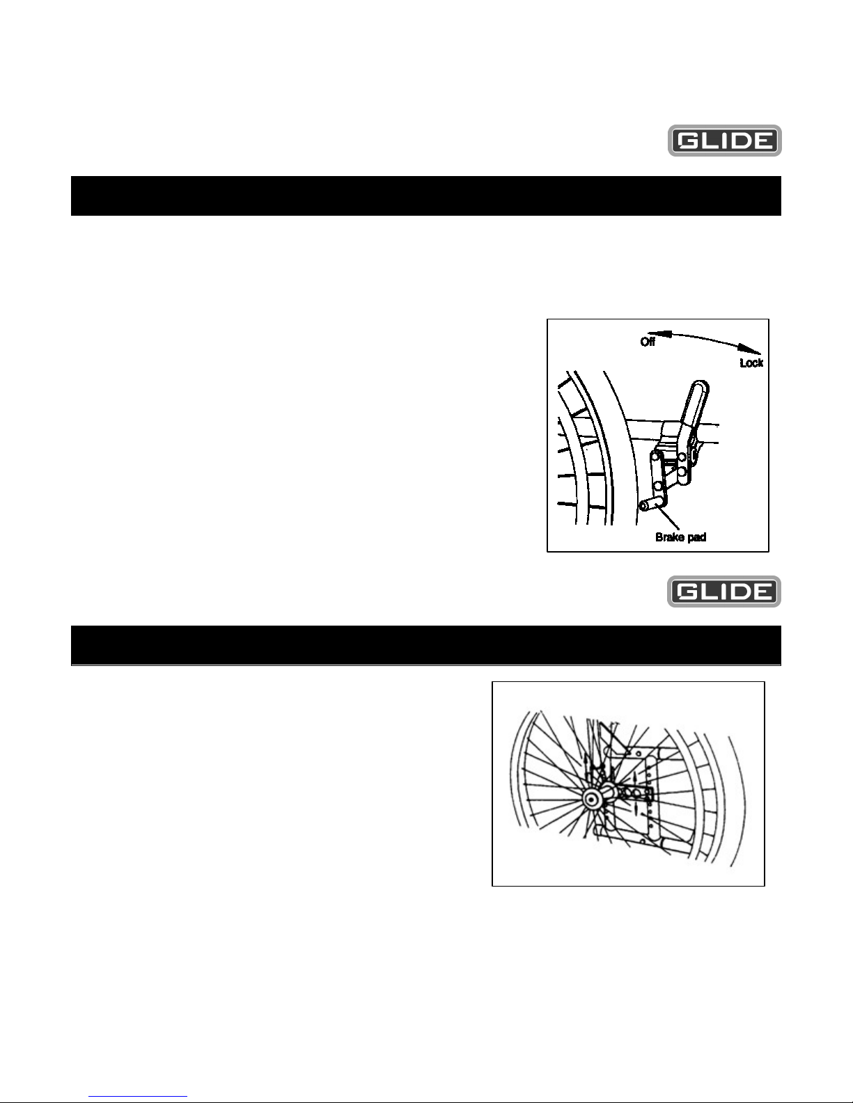
Large wheels (quick release)
•To remove large wheels (quick release) push button in and slide wheel out while button
is still depressed.
•To install push button in and slide wheel in.
•Wheels should be removed weekly and axles and sockets wiped clean with a soft cloth
to avoid jamming in the socket. Smear axle with dri-lube stick before replacing.
Warning
•Do not use wheelchair, unless button is fully out when wheels are in place.
8
Section 9
Brakes
•Brakes are designed as a locking device only and should only be applied when the
wheelchair is stationary. Do not use brakes for slowing the wheelchair. Use the
pushrims as a means of braking.
Adjusting Brakes
•Inflate tyre to correct pressure before making
adjustment to brakes.
•Loosen locking screws on brake body and adjust
brake pad so when lever is in the locked position the
wheel is firmly locked.
•Re-tighten lock nuts.
•Check that when both brakes are applied, the
wheelchair will not roll.
If rolling occurs readjust.
•When brakes are in the off position the bars should not
rub against the tyre.
Section 10
Rear Wheel Position
The rear wheels are adjustable both vertically and
horizontally.
To adjust vertically.
Remove the rear wheels and the 4 bolts holding the
axle plate. Move plate up and down to the desired
height. Replace bolts and tighten. Avoid over
tightening bolts as the frame may be damaged.
To adjust horizontally.
Remove the rear wheels and axle plate from frame.
Remove axle socket and place in the required hole. Half hole adjustments can be achieved by
reversing axle plate. Replace axle socket and tighten.

9
Caution
Increasing the seat fall and moving wheels forward will greatly affect the stability of the
wheelchair.
Section 11
Folding and opening the wheelchair
Opening
•Standing in front of the wheelchair, using two hands slowly press down on both seat
tubes keeping both hands on top of the seat at all times. As the wheelchair folds out
you will notice more pressure is required to open the chair until it reaches a point
where it will suddenly snap into position.
Caution
Never wrap hands around the seat tube when opening the wheelchair or have any part of the
hand protruding further than the seat width as injury may occur.
Folding
Before folding flip footplates to the up position.
Standing to one side of the wheelchair, grasp the seat upholstery front and rear,
approximately centre and lift upwards. You may find that a quick jerking action may be
necessary for the chair to release from the locked position.
Section 12
Cross Brace
•The cross brace centre bolt should be kept tight. Over tightening will make wheelchair
difficult to fold.

10
Section 13
Tyres / Castor Tyres
•Worn and under inflated tyres will render the wheelchair difficult to steer and propel.
Large wheel tyres and castor tyres should be only replaced in pairs.
Anti Tip Wheels
•When anti-tip wheels are required, please contact your nearest Glide Rehabilitation
Products dealer for correct fitting procedures.
Warning
Interference with kerbs may occur when anti tip wheels are fitted.
Other manuals for G2 Series
1
This manual suits for next models
1
Table of contents
Other Glide Wheelchair manuals

Glide
Glide TS TILT User manual

Glide
Glide 4 Series User manual

Glide
Glide G1 Series User manual

Glide
Glide SERIES 8 User manual

Glide
Glide COMFORT-PLUS DELUXE User manual

Glide
Glide CentroGlide User manual

Glide
Glide Rehabilitation Products User manual

Glide
Glide SPX User manual

Glide
Glide 6 Series User manual

Glide
Glide RoboGlide User manual