geotomographie MBAS-D User manual
Operation and Maintenance Manual May 2023
page 1
Geotomographie GmbH, Am Tonnenberg 18, 56567 Neuwied (Germany)
Tel.: +49 2631 778135 email: info@geotomographie.de
MBAS-D
Digital Multistation Borehole
Acquisition System

Operation and Maintenance Manual May 2023
page 2
Geotomographie GmbH, Am Tonnenberg 18, 56567 Neuwied (Germany)
Tel.: +49 2631 778135 email: info@geotomographie.de
Content
1. Introduction ............................................................................................................................................................ 3
2. General set-up of the MBAS-D .............................................................................................................................. 3
3. 3C Sensor Orientation ............................................................................................................................................ 6
4. Software MBAS-D .................................................................................................................................................. 6
5.1 Connection to 1st Station Probe Head ................................................................................................................. 7
5.2 Connecting Probes .............................................................................................................................................. 9
5.3 End connector ................................................................................................................................................... 10
5.4 Air Supply and Pressure Scheme ...................................................................................................................... 11
5.5 Re-Number Stations .......................................................................................................................................... 12
6. Some Technical Parameters ................................................................................................................................. 13
7. Recommended Software Settings ........................................................................................................................ 14
8. Handling instructions in the field ........................................................................................................................ 15
Operation and Maintenance Manual May 2023
page 3
Geotomographie GmbH, Am Tonnenberg 18, 56567 Neuwied (Germany)
Tel.: +49 2631 778135 email: info@geotomographie.de
1. Introduction
High-resolution P-wave tomographic investigations between boreholes are routinely applied for the
exploration of development sites considered for larger building projects, e.g. power stations, dams and
high-rise buildings. However, the geotechnical benefits of P-wave tomography are rather limited and
information about S-wave velocity distribution is additionally required to derive geotechnically relevant
parameters, such as dynamic soil parameters. Up to now, only little efforts have been made to develop
equipment enabling the competitive acquisition of S-wave crosshole tomographic data.
The Multistation Borehole Acquisition System (MBAS-D) is designed to efficiently acquire S-waves in
dry and water-filled boreholes at different levels. The system is digital and does not require a
seismograph. Each station is equipped with a 3C sensor array and is pneumatically coupled to the
borehole wall by two pressure cylinders.
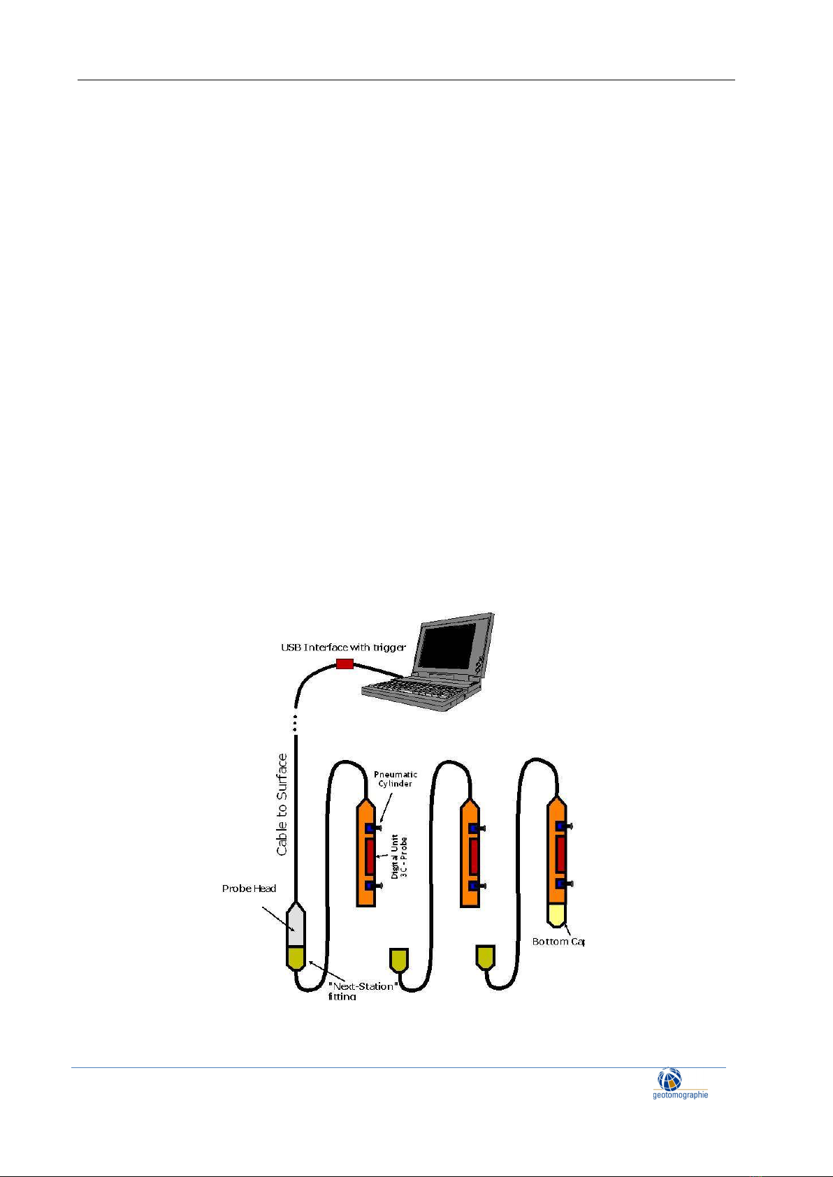
2. General set-up of the MBAS-D
The Digital Multistation Borehole Acquisition System (MBAS-D) is a digital three-component geophone
string which does not require a separate seismograph. Up to ten individual stations with a tri-axial sensor
array can be connected. The stations are aligned to ensure that all horizontal sensors are oriented in same
direction meaning that all X and Y components are aligned. To orientate the MBAS to an optimum
recording position, a rotating string hose is used. The hose is flexible for winding on a drum, but stiff
when trying to rotate it. This makes it easy to turn the MBAS in any direction.
Figure 1: General set-up of the MBAS-D
Operation and Maintenance Manual May 2023
page 4
Geotomographie GmbH, Am Tonnenberg 18, 56567 Neuwied (Germany)
Tel.: +49 2631 778135 email: info@geotomographie.de
Each station is clamped to the borehole wall by two pneumatic cylinders.
An external trigger can be plugged into the USB interface on surface which is connected to a laptop. The
operation is entirely controlled by the acquisition software. A separate seismograph is not required.
Additional 3C stations can be added by simply plugging them into the bottom last station.
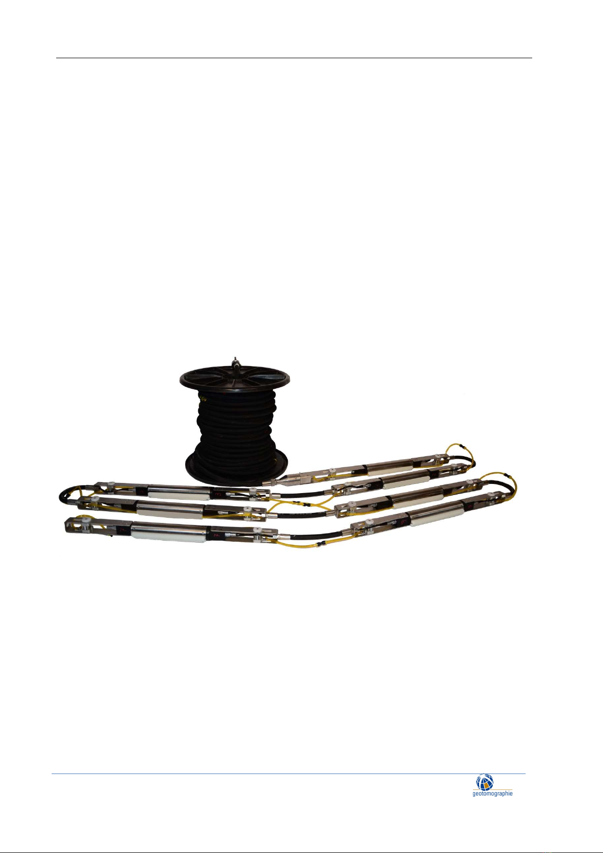
The MBAS-D system consists of
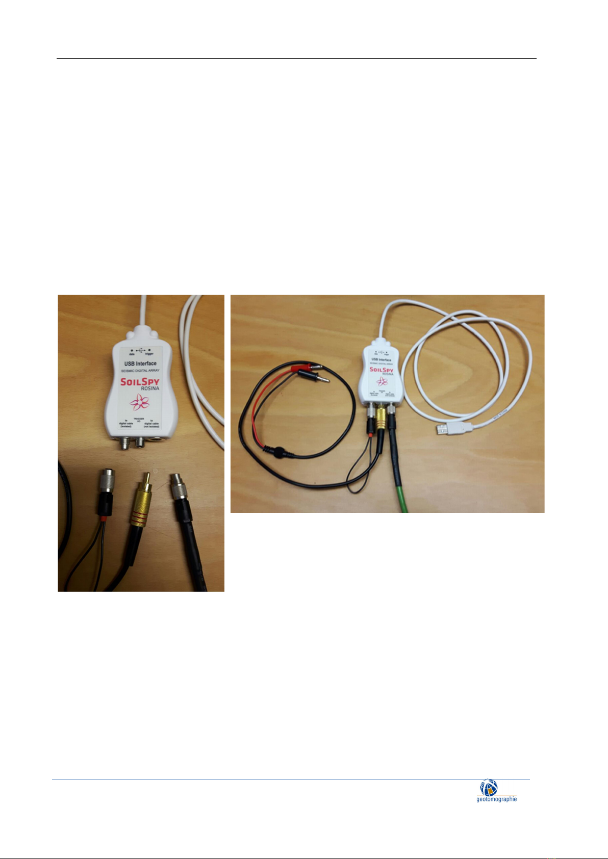
(1) USB interface with cables (USB to laptop, trigger cable, dead end plug) (see Figure 2)
(2) MBAS-D Rotary string on drum with surface connector and probe head (see Figure 3)
(3) MBAS-D stations (N x of 3C stations, maximum number of stations 10) (see Figure 4)
(4) Software
Figure 2: USB Interface with USB connection to laptop, trigger cable, cable to string and small surface
end plug

Operation and Maintenance Manual May 2023
page 5
Geotomographie GmbH, Am Tonnenberg 18, 56567 Neuwied (Germany)
Tel.: +49 2631 778135 email: info@geotomographie.de
Figure 3: MBAS-D Rotary String
Figure 4: MBAS-D stations
Operation and Maintenance Manual May 2023
page 6
Geotomographie GmbH, Am Tonnenberg 18, 56567 Neuwied (Germany)
Tel.: +49 2631 778135 email: info@geotomographie.de
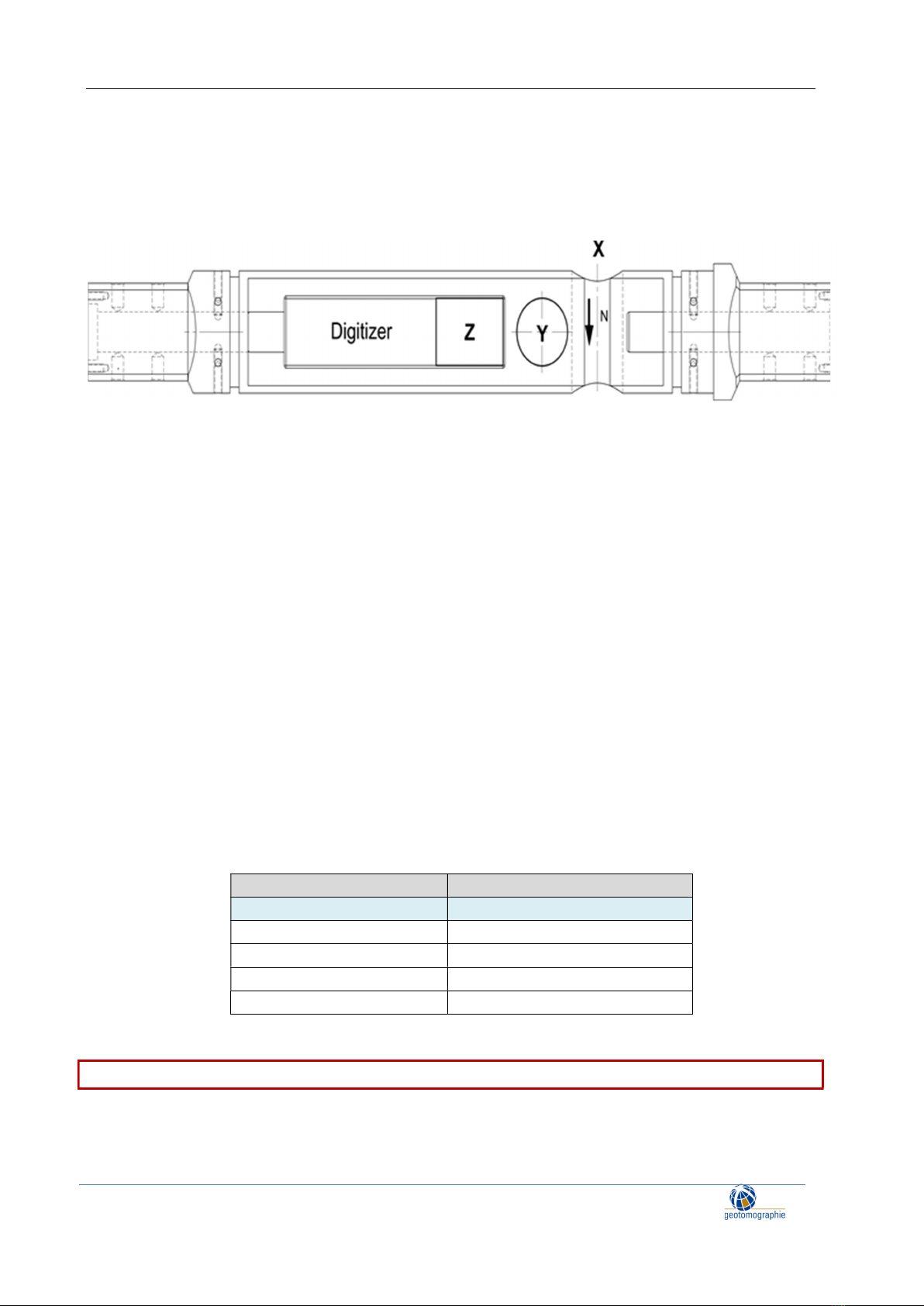
3. 3C Sensor Orientation
Each station is equipped with a digitising unit and a 3C geophone system. The X-direction points to the
north, i.e. in the direction of the pneumatic cylinders.
Figure 5: Station with 3C sensor orientation
4. Software MBAS-D
The MBAS-D software is provided in cooperation with company Moho (www.moho.world). It is their
proprietary versatile software SoilSpy Rosina software. For software instructions please refer to the
SoilSpy Rosina software manual.
SoilSpy Rosina is the software tool used to establish communication with the MBAS-D stations, to
acquire recordings and to store data on a PC.
Note: For the system to work, the SoilSpy Rosina USB interface must be recognised by the PC operating
system as a COM (communication) port. To do this, you will need to install the USB interface driver.
Please follow the instructions in the SoilSpy Rosina manual (see PC Settings).
Note that the trigger channel is set to USB. Station channels can be renumbered if a station is lost or has
a poor signal.
Function Channel Number
Trigger USB
1
st
Station 1 (X),2 (Y),3 (Z)
2
nd
Station 4 (X),5 (Y),6 (Z)
3
r
d
Station 7(X), 8(Y), 9(Z)
… …
It is essential that the channels are numbered starting from 1.

Operation and Maintenance Manual May 2023
page 7
Geotomographie GmbH, Am Tonnenberg 18, 56567 Neuwied (Germany)
Tel.: +49 2631 778135 email: info@geotomographie.de
5. Hardware MBAS-D
5.1 Connection to 1st Station Probe Head
The MBAS-D hardware consists of the USB interface, a trigger channel, the cable connection to the
MBAS-D stations and the MBAS-D stations. Figure 6 shows the arrangement from PC to probe head.
Figure 6: MBAS-D arrangement up to probe head
Arrangement:
1: Laptop with USB Port
2: USB Interface with USB cable and connector to trigger
3: Surface connector with cable take out to trigger and air take out
4: Probe head with LEMO 4 pin socket and air connector
Depth reference is the middle of the uppermost 3C station. To get total depth of lowest station you
may add the number of all station N-1 times the spacing between the stations
1
2
3
4

Operation and Maintenance Manual May 2023
page 8
Geotomographie GmbH, Am Tonnenberg 18, 56567 Neuwied (Germany)
Tel.: +49 2631 778135 email: info@geotomographie.de
Connect the first station to the probe head (see Figure 7) and connect the data cable and air hose (see
Figure 8).
Figure 7: Screw first station to probe head
Figure 8: Connect data cable (tightly) and air hose
Operation and Maintenance Manual May 2023
page 9
Geotomographie GmbH, Am Tonnenberg 18, 56567 Neuwied (Germany)
Tel.: +49 2631 778135 email: info@geotomographie.de
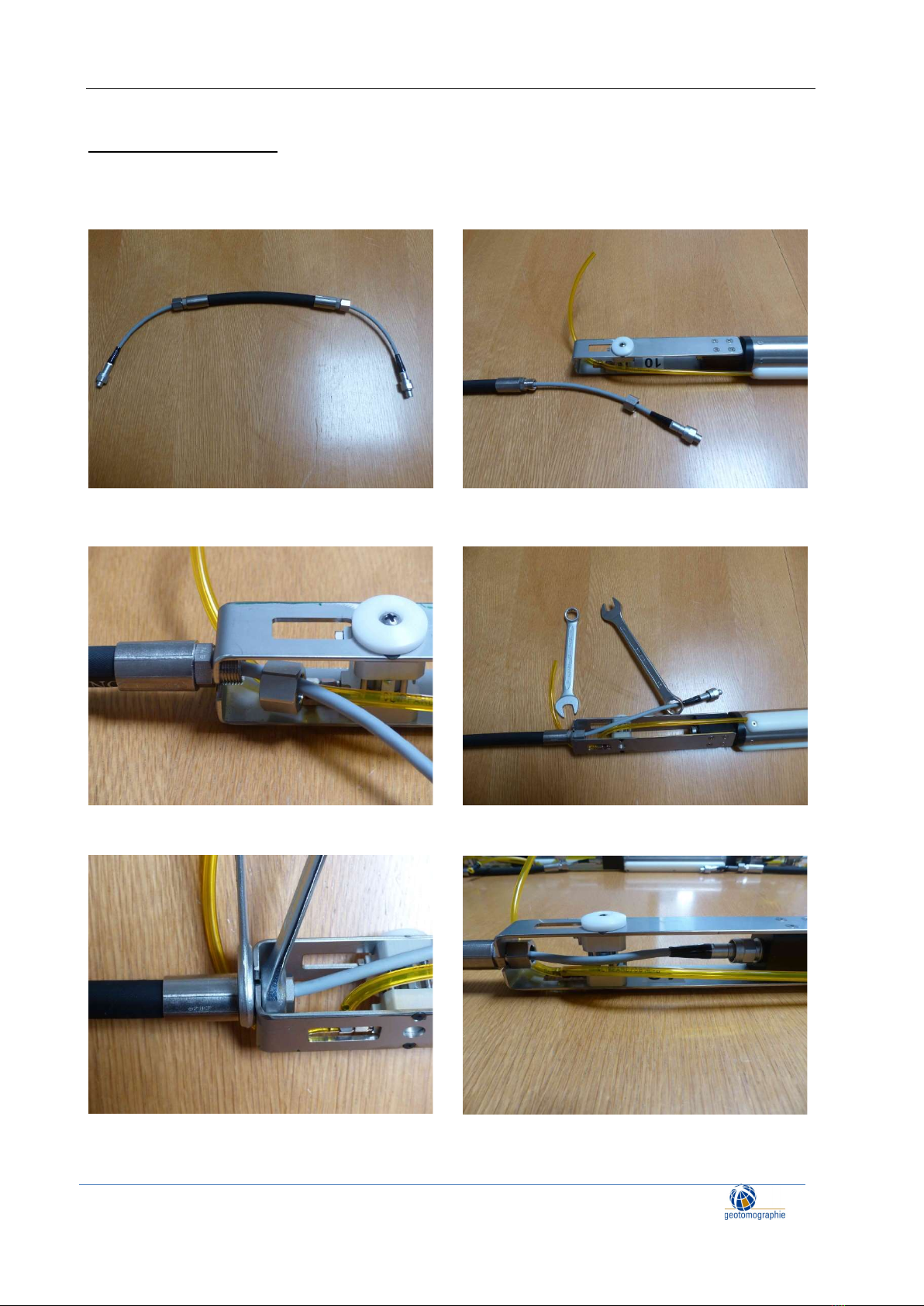
5.2 Connecting Probes
To connect stations use the connecting cable and follow the procedure shown in Figure 9 to Figure 14.
Ensure that all probes are aligned in same direction.
Figure 9: Station Connecting Cable Figure 10: Put data cable trough side opening
Figure 11: Screw nut Figure 12: Use box wrench and spanner
Figure 13: Fit tightly Figure 14: Connect data cable to probe
Operation and Maintenance Manual May 2023
page 10
Geotomographie GmbH, Am Tonnenberg 18, 56567 Neuwied (Germany)
Tel.: +49 2631 778135 email: info@geotomographie.de
Fasten the data cable to the 3C probe finger-tight.
Push in and screw.
Push in again and screw until the connector cannot be pushed in any further.
Screw as tightly as possible.
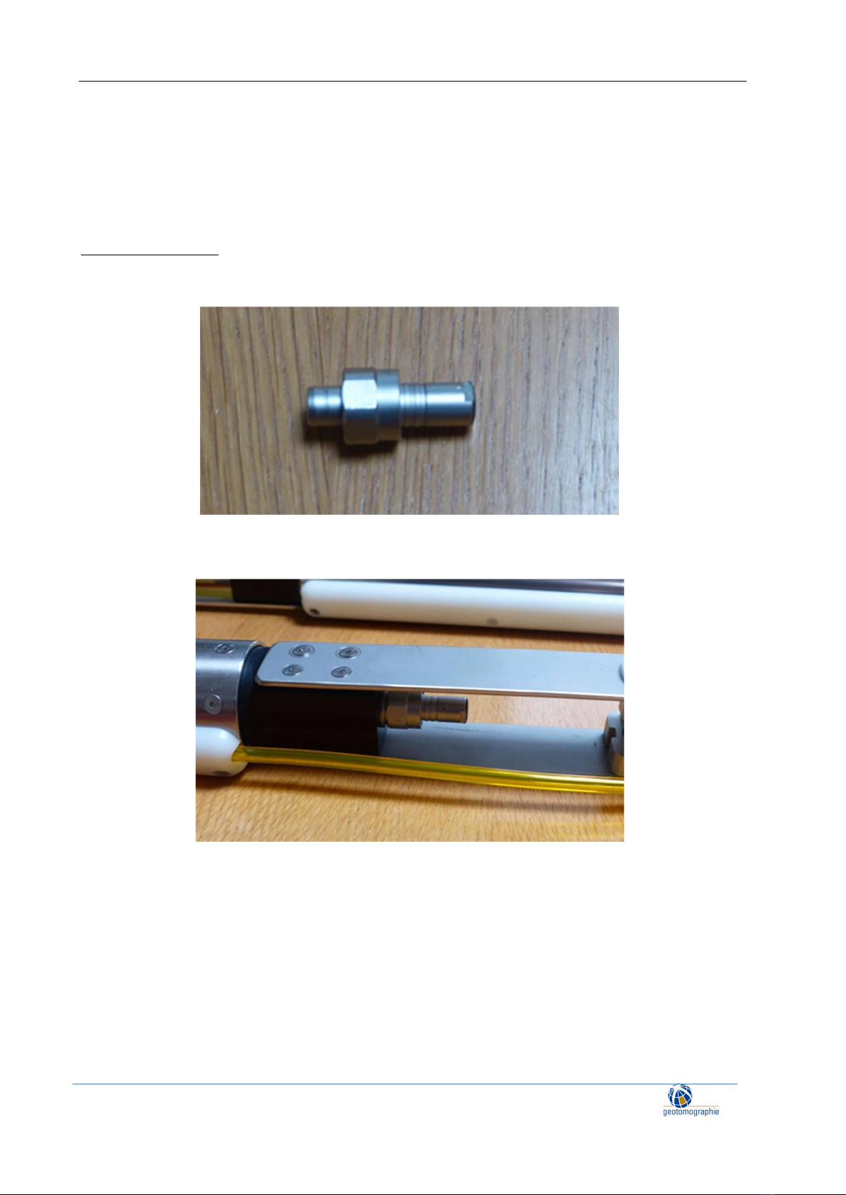
5.3 End connector
Fit the end connector (see Figure 17) to the bottom 3C station as tightly as possible to terminate
the data link.
Figure 17: End connector
Figure 18: End connector attached
Table of contents
Other geotomographie Test Equipment manuals


