Geo-Flo NP Series Installation guide

www.geo-o.com
NP Base Non-Pressurized Flow Centers
Installaon, Operang, and Maintenance Manual
Geo-Flo Corporaon
905 Williams Park Drive
Bedford, Indiana 47421, U.S.A.
Main Number: 812-275-8513
Toll Free: 800-784-8069
Fax: 888-477-8829

THIS PAGE INTENTIONALLY LEFT BLANK

NPBSeriesNon-PressurizedFlowCenters
Table of Contents
General Descripon . . . . . . . . . . . . . 1
Available Flow Center Models . . . . . . . . 2
Flow Center Pump Sizing. . . . . . . . . . . 5
Installaon . . . . . . . . . . . . . . . . 6
Flushing and Purging . . . . . . . . . . . . 8
Start Up . . . . . . . . . . . . . . . . . .13
Maintenance. . . . . . . . . . . . . . . .15
Pump High Voltage Wiring . . . . . . . . . .17
Oponal Pressure Relief Piping . . . . . . . .18
Troubleshoong . . . . . . . . . . . . . .19
NOTES:
This guide provides the installer with instrucons specic to NP Base Flow Centers. Please refer to your
heat pump manufacturer’s instrucons or CSA/ANSI/IGSHPA guidelines for addional detailed ushing,
purging, and installaon informaon. Please review the enre IOM document before proceeding with
the installaon.
Geo-Flo Corporaon is connually working to improve its products. As a result, the design and
specicaons of products in this catalog may change without noce and may not be as described
herein. For the most up-to-date informaon, please visit our website, or contact our Customer Service
Department. Statements and other informaon contained in this document are not express warranes
and do not form the basis of any bargain between the pares, but are merely Geo-Flo’s opinion or
commendaon of its products.
General Descripon
The NP Series is a family of non-pressurized ow centers used for
closed-loop geothermal (ground source) heat pump systems. The
NP Series ow centers ulize a water column to provide the neces-
sary sucon head for the circulator pump, and to ensure a ooded
pump volute. Each NP Series ow center consists of a uid reservoir
(tank), ush and/or service/isolaon valves, and one or more pumps
housed in a foam-insulated cabinet. The valves included in each NP
ow center varies within the family of products. Review the follow-
ing secon on “Available NP Flow Center Models” for more informa-
on. Every NP ow center includes a sealing cap to ensure a closed
system and provides vacuum relief to prevent the reservoir from
dropping below atmospheric pressure when the loop expands (dur-
ing cooling season). A pressure relief valve prevents the reservoir
from being over-pressurized when the loop contracts (during heang
season). Since the NP reservoir can hold pressure, the air space at
the top funcons like an expansion tank in pressurized systems. The
NP reservoir provides an air separaon funcon due to the size of
the tank and design of the return piping.
1 | Installaon, Operang, and Maintenance Manual
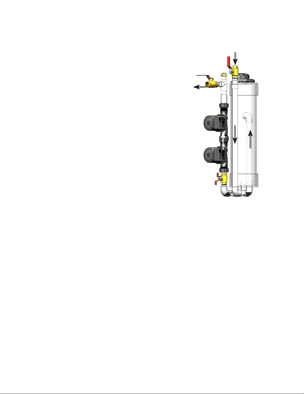
Figure 1 shows the uid ow to and from the NP Base ow center. The uid is pumped from the ow center’s
tank on the le side, travels up through the sucon side isolaon valve, through the pump(s), and out the dis-
charge isolaon valve . The uid returns from the ground loop through the top right tank isolaon valve and is
directed to the tank where any air present in the uid is released.
Figure 1: Generalized uid ow
(components inside cabinet)
Out: From
Flow Center
to Heat Pump
In: From
Ground Loop
to Flow Center
To tank
From tank
Available Models
The NP Series of ow centers are available in several
models to meet the requirements of the specic instal-
laon and contractor preference. The following is a
brief descripon of each NP product. Note that each NP
product has a specic installaon manual. This manual
focuses on the NP Base. Consult the manuals for each
specic NP for further informaon.
NP Base (NPB) Flow Center:
The NP Base is a cost compeve model designed for
single geothermal heat pump installaons (one heat
pump on a dedicated ground loop) where the contrac-
tor chooses to install external ush valves, or chooses to
ulize internal headers (i.e. all loop circuits are brought
into the mechanical room). The NPB includes isolaon
valves on the pump sucon and discharge, and an isola-
on valve on the return. Field connecons to the NPB
are 1” NPT.
NP Flow Center:
The standard NP Flow Center is the original NP oering
and includes Geo-Flo’s Flo-Link double O-ring technology.
The NP is designed for single geothermal heat pump
installaons. The NP includes 3-way, 4-posion ushing
and isolaon valves that allow the contractor to ush the
heat pump and ground loop without addional valves or
plumbing. This NP may also be used with internal head-
ers. The 3-way valve on the sucon side of the pump(s)
can also be ulized to ll and drain the tank. The NP
Flow Center does not ship with any ngs. Hose kits are
available for installaon ease and exibility.
NPB Series Non-Pressurized Flow Centers | 2
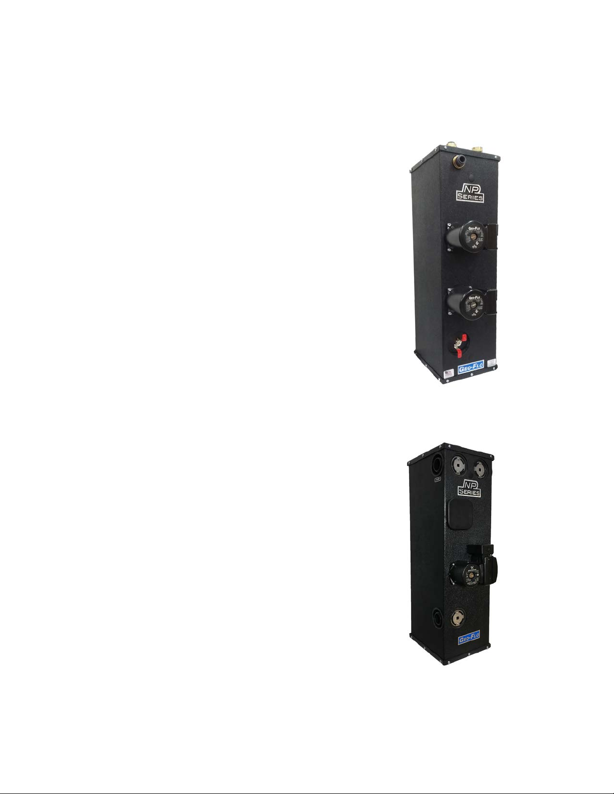
Figure 2: NPB
Figure 3: Standard NP

NP Plus (NPP) Flow Center
The NP Plus has the same features as the NP but also includes an
external 3-way ushing/purging valve, and a set of Flo-Link X 1-1/4”
HDPE socket fusion ground loop adapters (Figures 4 and 5). This ad-
dional external 3-way valve allows the ground loop to be ushed
separately from the heat pump. Since the ground loop adapters
are included, a hose kit or a set of Flo-Link double O-ring adapters
are all that is required for connecon to the heat pump. The NP is
designed for single geothermal heat pump installaons.
NP Dual Circuit (NPD) Flow Center
The NPD has the same features as the NP and NPP but is designed
for installaons where two geothermal heat pumps share the same
ground loop. All 3-way valves are built into the NPD. Check valves
are included in the product to prevent the need to install external
check valves on each pump circuit. Hose kits are available for instal-
laon ease and exibility.
Figure 5: NPP
Figure 4: NPP with hose kit
Figure 6: NPD
3 | Installaon, Operang, and Maintenance Manual
NP Mul Circuit (NPM) Flow Center
The NPM is a family of mul-circuit non-pressurized ow centers that are used for two or more geothermal
heat pumps sharing the same ground loop. Since there are large number of available opons for the NPM,
please consult our website or the NPM literature for detailed descripons.
NPB Series Non-Pressurized Flow Centers | 4
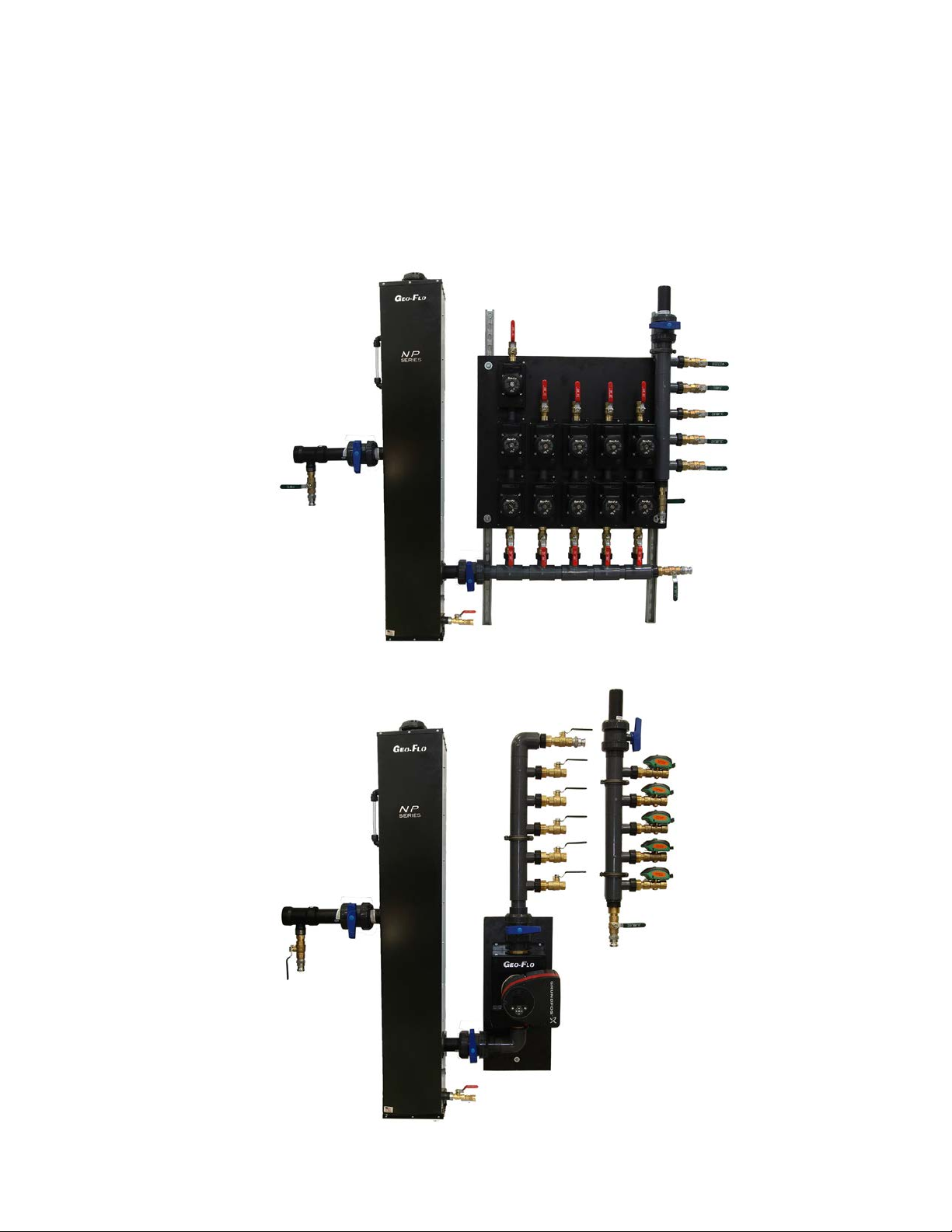
Figure 7: NPM with circulators for each heat pump
Figure 8: NPM with central variable speed pump and zone valves for each heat pump

Flow (U.S. GPM) [l/s]
Grundfos Pump Performance Curves (Single Pump)
Head (Feet) [kPa]
UP26-116 UPS26-99 high spd UPS26-99 med spd UPS26-99 low spd
[0.13 0.25 0.38 0.50 0.63 0.76 0.88 1.00 1.14 1.26 1.39 1.51 1.64 1.77 1.89 2.02 2.15 2.27]
[14.9]
[29.8]
[44.8]
[59.7]
[74.6]
[89.5]
[104.5]
[119.4]
Flow (U.S. GPM) [l/s]
Grundfos Pump Performance Curves (Two Pumps)
Head (Feet) [kPa]
2 UP26-116 2UPS26-99 high spd 2 UPS26-99 med spd 2 UPS26-99 low spd
[0.13 0.25 0.38 0.50 0.63 0.76 0.88 1.00 1.14 1.26 1.39 1.51 1.64 1.77 1.89 2.02 2.15 2.27]
[29.8]
[59.7]
[89.5]
[119.4]
[149.3]
[179.1]
[208.9]
[238.8]
5 | Installaon, Operang, and Maintenance Manual
Flow Center sizing:
Performance curves
The specic NP Series ow center should be selected based on the system pressure drop (including the geo-
thermal heat pump, ground loop piping, and interior piping). Calculators to assist with pressure drop deter-
minaon and pump selecon are available at www.geo-o.com/calculators. The ow center selected should
provide at least the minimum amount of ow recommended by the heat pump manufacturer for the heat
pump selected.
NOTE: The NP Base (NPB) is currently oered with UPS26-99 and UP26-116 pumps only. NP, NPP, NPD, and
NPM ow centers have addional pump opons.

NPB Series Non-Pressurized Flow Centers | 6
Installaon
Mounng the unit
The NP Series ow center must be mounted on a level surface
near the ground source heat pump. The unit can be placed on
the oor or on an isolaon pad such as a small piece of expanded
polystyrene (blue board insulaon) or a high-density rubber equip-
ment pad. Since the cabinet is plasc and will not rust, an isolaon
pad is not required for a thermal break but may be used if desired.
An-p brackets and hardware are included and can be used if
deemed necessary for the installaon locaon. If these brackets
are used, several methods of aachment can be ulized. Figures
9a, 9b, and 9c show these methods. Note that if you chose to
mount the NP to a concrete oor, the concrete anchors must be
eld provided.
Figure 9c:
Figure 9b:
Figure 9a: An-p brackets (two included)
mounted on top sides of ow center
An-p brackets mounted on
boom of ow center
An-p brackets mounted on top
of ow center
Plumbing Opons
The NPB Series ow center can be plumbed with a wide variety
of materials including HDPE, PVC, copper, PEX, and exible hose
to provide many opons to the installer. The ow direcons to
and from the ow center are shown in Figure 10. The installer can
choose to direct the uid ow from the pump(s) to the geother-
mal heat pump out the top or the front of the ow center. The
included isolaon valve should be installed in the chosen direc-
on, and the included 1” plug should be installed in the unused
port. The brass swivel half-union ngs use a at gasket and
should be torqued hand-ght plus 1/8 to 1/4 turn onto the valves
and plug. Over torquing may cause the joint to leak. If the joint
drips at start-up, snug with channel locks unl the drip stops.
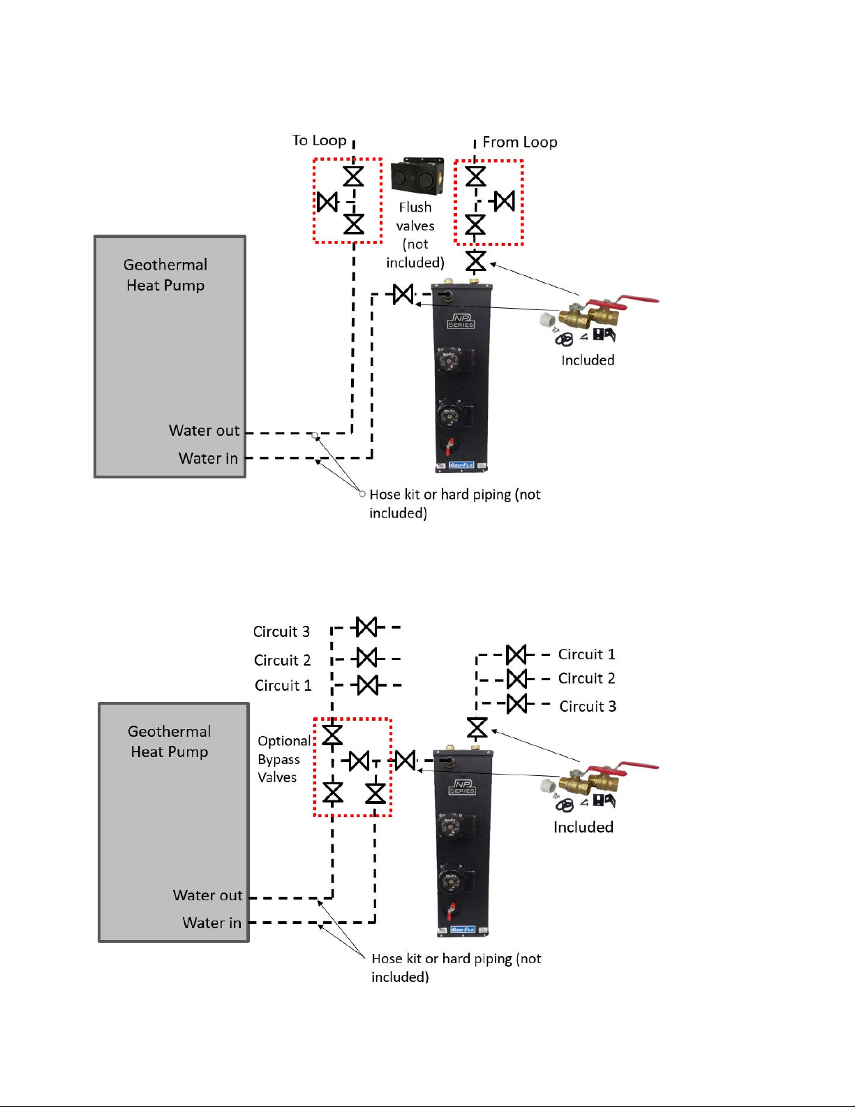
Figure 11 shows a standard installaon when the ground loop
headers are external to the building. Insulated 3-way ush valves
are available, or the installer may choose to install six ball valves
for ushing the loop and heat pump. Figure 12 shows an installa-
on where each loop circuit is brought into the mechanical room
and headered.
To HP
Opon 2
To HP
Opon 1
From
Loop
Figure 10: Flow Direcon
7 | Installaon, Operang, and Maintenance Manual
Figure 11: Plumbing diagram- external headers
Figure 12: Plumbing diagram- internal headers
Plumbing Opons: External Headers
Plumbing Opons: Internal Headers
Table of contents
Other Geo-Flo Water Pump manuals

Popular Water Pump manuals by other brands


Sykes AmeriPumps
Sykes AmeriPumps GP100M Operation and maintenance instructions

DUROMAX
DUROMAX XP WX Series user manual

BRINKMANN PUMPS
BRINKMANN PUMPS SBF550 operating instructions

Franklin Electric
Franklin Electric IPS Installation & operation manual

Xylem
Xylem e-1532 Series instruction manual

Milton Roy
Milton Roy PRIMEROYAL instruction manual