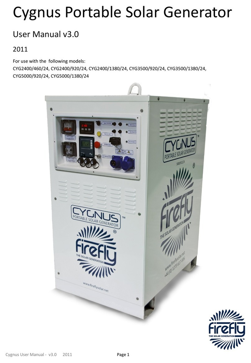
GENMAX GM4000iSBEPC User manual

GM4000iSBEPC Portable Inverter Generator
3200 Running Watts | 4000 Peak Watts
INVERTER GENERATOR
USER'S MANUAL
RGENMAX GENERATOR
WARNING: SAVE THIS MANUAL FOR FUTURE REFERENCE
This manual contains important information regarding safety. Operation,
maintenance and storage of this product. Before use, read carefully and
understand all cautions, warnings, instructions and product labels. Failure to do
so could result in serious personal injury and/or property damage.
1
UNPACKING
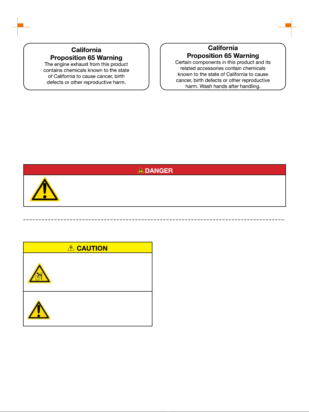
Always have assistance when lifting
the generator. The generator is heavy;
lifting it could cause bodily harm.
Avoid cutting on or near staples to
prevent personal injury.
Tools required - box cutter or similar device.
1. Carefully cut the packing tape on top of the carton.
2. Remove socket wrench, and oil funnel and save for
later.
3. Carefully cut two sides of the carton to remove the
generator.
WHAT COMES IN THE BOX
Spark Plug Socket Wrench (1)
Dual-Purpose Screwdriver (1)
User Manual (1)
Warranty Information (1)
Funnel (1)
30A 120V L14-30P to TT-30R Plug Adapter (1)
DISCLAIMERS:
All information, illustrations and specifications in this manual are based on the latest information available at the
time of publishing. The illustrations used in this manual are intended as representative reference views only.
Moreover, because of our continuous product improvement policy, we may modify information, illustrations and/or
specifications to explain and/or exemplify a product, service or maintenance improvement. We reserve the right to
make any change at any time without notice. Some images may vary depending upon which model is shown.
ALL RIGHTS RESERVED:
No part of this publication may be reproduced or used in any form by any means - graphic, electronic or
mechanical, including photocopying, recording, taping or information storage and retrieval systems - without the
written permission of CHONGQING DINKING POWER MACHINERY CO., LTD
This manual contains important instructions for operating this inverter generator. For your
safety and the safety of others, be sure to read this manual thoroughly before operating the
generator. Failure to properly follow all instructions and precautions can cause you and others
to be seriously hurt or killed.
2
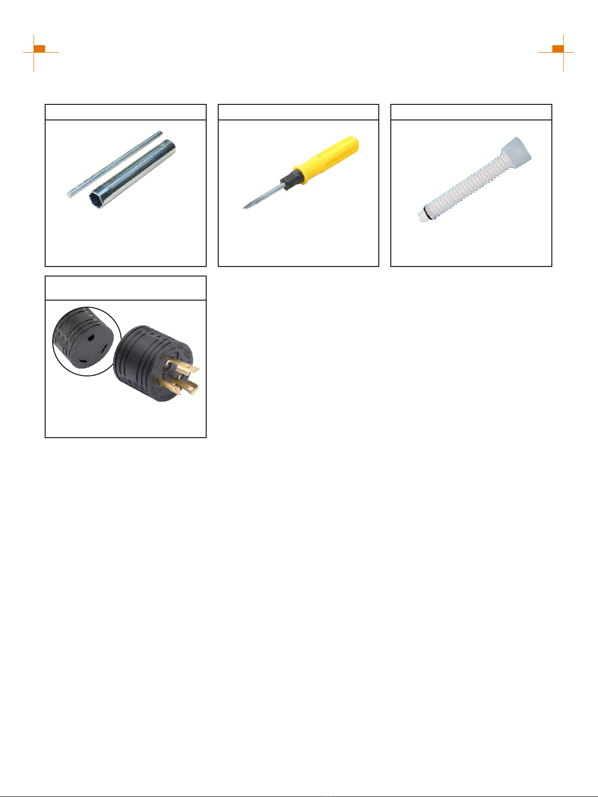
Spark Plug Socket Wrench
Used in spark plug maintenance,
inspection, and installation.
Phillips and slot blade
screwdriver used for generator
maintenance.
Dual-Purpose Screwdriver Funnel
It's used to oil the generator.
DESCRIPTION OF FITTINGS
30A 120V L5-30P to TT-30R
Plug Adapter
Change the 30A 120V L5-30R
socket to the TT-30R socket.
Note: Actual tools may differ in appearance or design from image shown.

3
LIMITED WARRANTY
1. DURATION : One (1) year from the date of purchase by the original purchaser ( retail customer ) on products used
solely for consumer applications; if a product is used for business, commercial, or industrial applications, the warranty
per iod will be limited to ninety (90) days from the date of purchase.
2. WHO GIVES THIS WARRANTY (WARRANTOR):
CHONGQING DINKING POWER MACHINERY CO., LTD
3. WHO RECEIVES THIS WARRANTY(PURCHASER):The original purchaser (other than for purposes of resale) of
the Genmax's inverter.
4. WHAT PRODUCTS ARE COVERED BY THIS WARRANTY: Any portable generator supplied or manufactured by
Warrantor.
5. WHAT IS COVERED UNDER THIS WARRANTY: Substantial defects on material and workmanship which occur
within the duration of the warranty period.
6. WHAT IS NOT COVERED UNDER THIS WARRANTY:
A. Transportation changes for sending the product to Warrantor or its authorized service representative for warranty
service, or for shipping repaired or replacement products back to the customer; these charges must be borne by the
customer.
B. Damages caused by abuse, accident, shipping, misuse, overloading, modification, and the effects of corrosion,
erosion and normal wear and tear.
C. Warranty is voided if the customer fails to install, maintain and operate the product in accordance with the
instructions and recommendations set forth in the owner's manual(s), or if the product is used as rental equipment.
D. Pre-delivery service, i.e. assembly, oil or lubricants, and adjustment.
E. Items or service that are normally required to maintain the product, i.e. lubricants and filters.
F. Warrantor will not pay for repairs or adjustments to the product, or for any costs or labour, performed without
Warrantor's prior authorization.
EXCLUSIONS AND LIMITATIONS: Warrantor makes no other warranty of any kind, express or implied. Implied
warranties, including warranties of merchantability and of fitness for a particular purpose, are hereby disclaimed. This
warranty service described above is the exclusive remedy under this warranty; liability for incidental and consequential
damages is excluded to the extent permitted by law.
7. RESPONSIBILITIES OF PURCHASER UNDER THIS WARRANTY:
A. The purchaser must provide dated proof of purchase and must notify Warrantor within the warranty period.
B. Deliver or ship the serviced generator or component to the nearest Warrantor's authorized service representative.
Freight costs, if any, must be borne by the purchaser.
8. HAVE QUESTIONS?
Email: warrantiessmallengines@gmail.com Phone: 866-960-2920
Model Number: _____________________________________
Name: ___________________________________________
Serial Number: ______________________________________
Street Address: ___________________________________
Date Purchased: ____________________________________
Purchased From: ____________________________________
City, State, ZIP: ____________________________________
Country: __________________________________________
Phone Number: ___________________________________
E-Mail: ___________________________________________
WARRANTY CARD
R

4
TABLE OF CONTENTS
LIMITED WARRANTY 3
SAFETY WARNING 5
SAFETY INSTRUCTIONS 6
NAMES OF COMPONENTS 8
CONTROL FUNCTIONS 9
PREPARATIONS 11
1.Fuel............................................................................................................................................11
2.Oil...............................................................................................................................................11
3.Pre-operation inspection............................................................................................................12
STARTING UP THE GENERATOR 13
SHUTTING DOWN THE GENERATOR 14
USING THE GENERATOR 15
1.Service environment of the generator.......................................................................................15
2.Generator wiring........................................................................................................................15
3.Generator grounding.................................................................................................................16
4.Battery Charging.......................................................................................................................17
5.Parallel operation......................................................................................................................18
SERVICE AND MAINTENANCE 19
1.Spark plug inspection...............................................................................................................20
2.Adjustment of the carburetor.....................................................................................................21
3.Replacement of oil....................................................................................................................21
4.Air filter......................................................................................................................................22
5.Fuel filter screen........................................................................................................................23
STORAGE AND TRANSPORT 24
1.Generator storage.....................................................................................................................24
2.Generator transport...................................................................................................................25
TROUBLESHOOTING 26
TECHNICAL PARAMETERS 28
CIRCUIT DIAGRAM 29
CHOOSING A GENERATOR 30
5
SAFETY WARNING
Personal and property safeties of you and others are very vital. Please read the Safety
Warning in the User's Manual and the decals of the generator set carefully.The Safety
Warning can alert you to those potential hazards that could harm you and others. In front
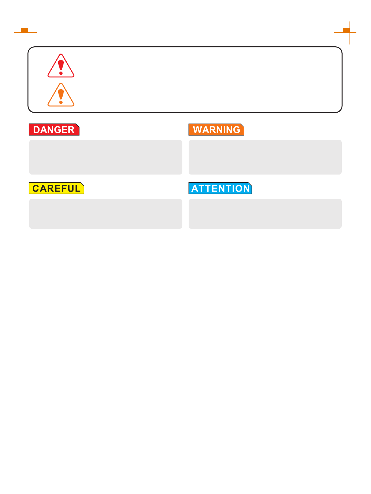
of each Safety Warning, there is one of four words "DANGER" "WARNING",
"ATTENTION", and "CAREFUL". Details are as follows:
Failure to follow the instruction will result in
being in peril of your life or extremely serious
injury.
Failure to follow the instruction will result in
being in peril of your life or very serious injury.
Failure to follow the instruction will result in
minor injury.
Failure to follow the instruction will result in the
damage to your generator set and other properties.
For portable generators where the neutral is floating, the operator's manual shall include the following wording
or equivalent:
The portable generator stator winding is isolated from the frame and from the AC receptacle ground pin; and
Electrical devices that require a connection between one conductor pin and the grounded receptacle pin may not
function properly.
NEUTRAL FLOATING
CO DETECT technology monitors the accumulation of carbon monoxide (CO), a poisonous gas produced by
engine exhaust when the generator is running. If CO Sensor detects unsafe elevated levels of CO gas, it
automatically shuts off the engine. CO Sensor is not a substitute for an indoor carbon monoxide alarm or for safe
operation. DO NOT allow engine exhaust fumes to enter a confined area through windows, doors, vents or other
openings. Generators must ALWAYS be used outdoors, far away from occupied buildings with engine exhaust
pointed away from people and buildings. Meets the requirements of ANSI/PGMA G300-2018.
CO TECHNICAL WARNING
6
SAFETY INSTRUCTIONS
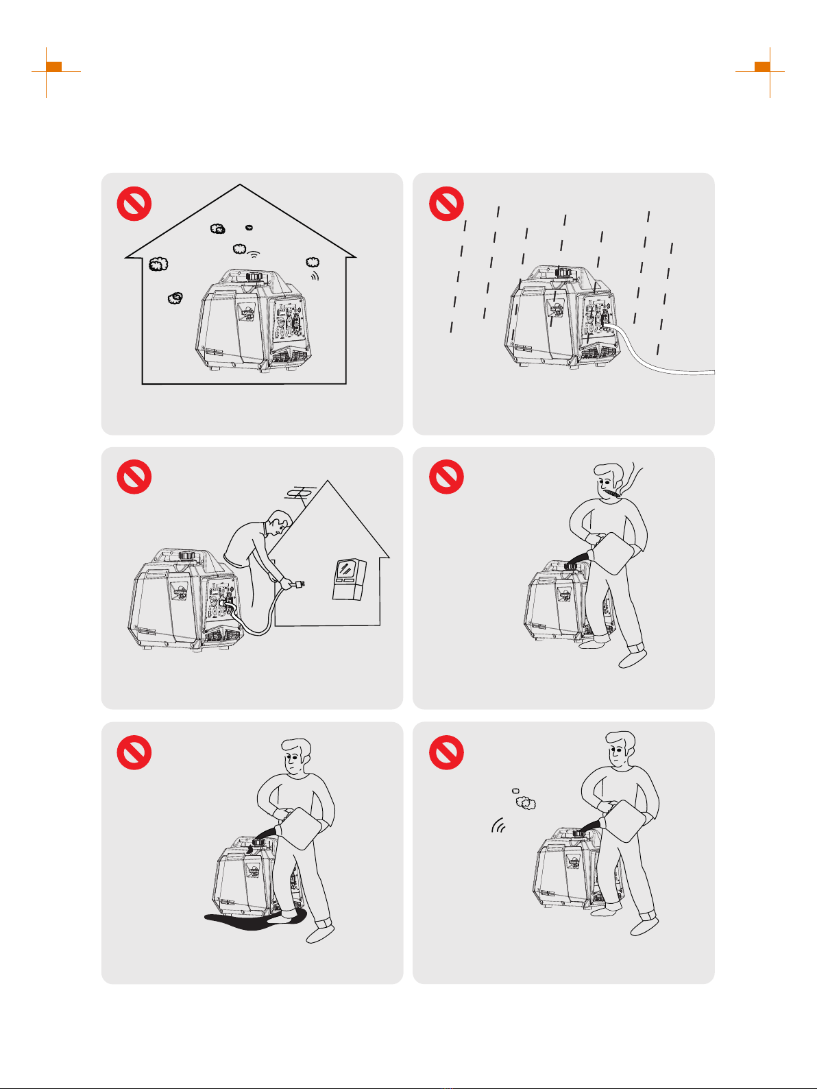
Before operating the generator, it will help you avoid accidents to read and understand the Manual
and familiarize yourself with the safe operation procedures of the generator.
Please do not use indoors Please do not use in humid
environment
Please do not connect it to
household appliances directly Please do not smoke when refueling
Please do not spill when refueling
Please shut down the generator
before refueling

7
SAFETY INSTRUCTIONS
SAFETY LABELS AND DECALS
6
6
8
NAMES OF COMPONENTS
1
2
3
4
9
10
3
7
8
6
5
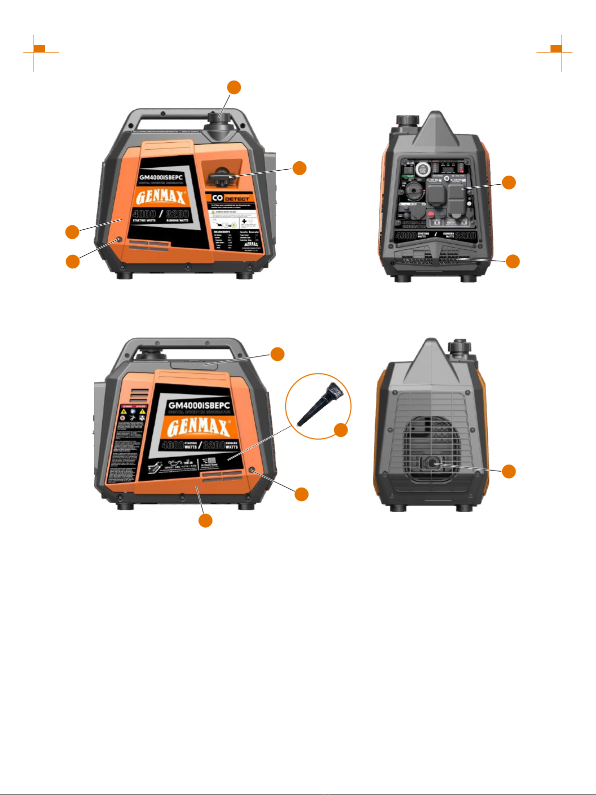
① Fuel Tank Cap: Open the fuel tank cap and fill with
proper amount of gasoline.
② Recoil Handle: Pull to start the engine.
③ Bolt: Remove left (right) outer cover.
④ Left Outer Cover
⑤ Control Panel: Contains the reset breaker, outlets
and warning lights.
⑥ Engine Cooling Vents: Helps move airflow in unit
to regulate engine temperatures.
⑦ Right Outer Cover: Unscrew the bolts to remove
the outer cover, add or replace the oil and maintain the
air filter.
⑧ Muffler: Avoid contact until the engine is cooled
down. The spark arrestor prevents sparks from exiting
the muffler. It must be removed for servicing.
⑨ Spark Plug Access Cover: Remove the cover to
service the spark plug.
⑩ Magnetic Oil Dipstick: absorb iron filings in the oil,
it is recommended to screw down the magnetic oil
dipstick and clean it every 50 hours.
9
CONTROL FUNCTIONS
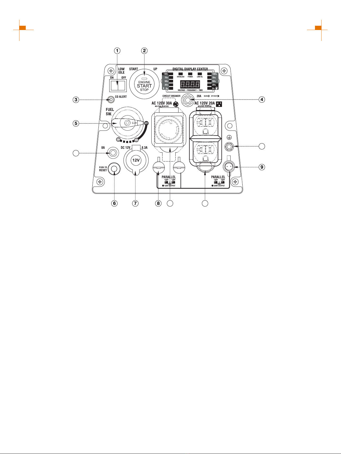
① Low Idle Switch: When turned to the ON position,
the engine will sense the load needed and run at a
slower RPM to save fuel.
② One Push Start: Press this button, the engine can
start and stop.
③ CO Alarm: Flashing red light: dangerous levels of
carbon monoxide gas have built up leave immediately
until area has aired out. Move generator to well-
ventilated area before operation. Flashing yellow light:
carbon monoxide sensor malfunction. Sensor needs
service.
④ AC Protector: If the generator is overload, the AC
protector will trip to block current.
⑤ Fuel Switch: Switch to ON to turn ON the fuel,
switch to OFF to turn OFF the fuel.
⑥ Reset: If the inverter is overloaded, the reset
breaker will trip. The engine will continue to run, but
there will be no output from the inverter. Unplug the
devices and reduce the load. Push in the reset breaker
to reset it.
⑦ DC Cigarette Lighter Outlet: 12V DC 8.3A.
⑧ Parallel Connectors: To increase AC power output,
the connector sockets are used to connect the two
same type generators with special parallel kit
GM6000SPK sold by GENMAX. The connector sockets
is only used to connect two inverter generators. They
can not used for AC power output. The special
paralleling kit GM6000SPK shall be purchased
separately, and they shall be approved by certification
body.
⑨ Parallel Connectors (240V OUTPUT): When using
parallel kits, two 120V generators can output 240V by
connecting this interface.
⑩ 120V AC 30A L5-30R Outlet: The outlet is capable
of carrying a maximum of 30 amps.
⑪120V AC 20A 5-20R Outlet: The outlet is capable of
carrying a maximum of 20 amps.
⑫Ground Terminal: The ground terminal is used to
externally ground the inverter.
⑬ DC Protector: If the generator is overload, the DC
protector will trip to block current.
CONTROL PANEL FEATURES GM4000iSBEPC
10 11
12
13
Table of contents
Other GENMAX Portable Generator manuals

GENMAX
GENMAX GM10500iETC User manual

GENMAX
GENMAX GM7250iEDC User manual

GENMAX
GENMAX GM2200i User manual

GENMAX
GENMAX GM5500i User manual

GENMAX
GENMAX GM2000i User manual

GENMAX
GENMAX GM1200i User manual

GENMAX
GENMAX PARALLEL KIT User manual

GENMAX
GENMAX GM5500i User manual

GENMAX
GENMAX GM2200i User manual

GENMAX
GENMAX GM6000iED User manual

GENMAX
GENMAX GM2800iSAC User manual

GENMAX
GENMAX GM2800iA User manual

GENMAX
GENMAX GM4600iAEDC User manual

GENMAX
GENMAX GM12000E User manual

GENMAX
GENMAX GM9000iED User manual

GENMAX
GENMAX GM12000ED User manual

GENMAX
GENMAX GM6000iE User manual

GENMAX
GENMAX GM9000iE User manual

GENMAX
GENMAX GM3500Xi User manual

GENMAX
GENMAX GM1200i User manual