GE 29418 User manual

29418
Two-line Speakerphone
with 12 Number Memory
User’s Gui e
We bring goo things to life.

2
EQUIPMENT APPROVAL INFORMATION
Your telephone equipment is approved for connection to the Public Switched Telephone Network and is in
compliance with parts 15 and 68 FCC Rules and Regulations and the Technical Requirements for Telephone
Terminal Equipment published by ACTA.
1Notification to the Local Telephone Company
On the bottom of this equipment is a label containing a unique identification number with the format
US:AAAEQ##Txxx. You must upon request provide this information to your telephone company. The ## in this
number is the Ringer Equivalence Number (REN) for the equipment.
The REN is useful in determining the number of devices you may connect to your telephone line and still have all
of these devices ring when your telephone number is called. In most (but not all) areas the sum of the RENs of all
devices connected to one line should not exceed 5. To be certain of the number of devices you may connect to your
line as determined by the REN you should contact your local telephone company.
Notes
• This equipment may not be used on coin service provided by the telephone company.
• Party lines are subject to state tariffs and therefore you may not be able to use your own telephone equipment if
you are on a party line. Check with your local telephone company.
• Notice must be given to the telephone company upon permanent disconnection of your telephone from your
line.
2Rights of the Telephone Company
Should your equipment cause trouble on your line which may harm the telephone network the telephone
company shall where practicable notify you that temporary discontinuance of service may be required. Where
prior notice is not practicable and the circumstances warrant such action the telephone company may temporarily
discontinue service immediately. In case of such temporary discontinuance the telephone company must: (1)
promptly notify you of such temporary discontinuance; (2) afford you the opportunity to correct the situation; and
(3) inform you of your right to bring a complaint to the Commission pursuant to procedures set forth in Subpart E
of Part 68 FCC Rules and Regulations.
The telephone company may make changes in its communications facilities equipment operations or procedures
where such action is required in the operation of its business and not inconsistent with FCC Rules and Regulations.
If these changes are expected to affect the use or performance of your telephone equipment the telephone
company must give you adequate notice in writing to allow you to maintain uninterrupted service.
INTERFERENCE INFORMATION
This device complies with Part 15 of the FCC Rules. Operation is subject to the following two conditions: (1) This device
may not cause harmful interference; and (2) This device must accept any interference received including interference
that may cause undesired operation.
This equipment has been tested and found to comply with the limits for a Class B digital device pursuant to Part 15 of
the FCC Rules. These limits are designed to provide reasonable protection against harmful interference in a residential
installation.
This equipment generates uses and can radiate radio frequency energy and if not installed and used in accordance
with the instructions may cause harmful interference to radio communications. However there is no guarantee that
interference will not occur in a particular installation.
If this equipment does cause harmful interference to radio or television reception which can be determined by turning
the equipment off and on the user is encouraged to try to correct the interference by one or more of the following
measures:
• Reorient or relocate the receiving antenna (that is the antenna for radio or television that is “receiving” the
interference).
• Reorient or relocate and increase the separation between the telecommunications equipment and receiving
antenna.
• Connect the telecommunications equipment into an outlet on a circuit different from that to which the receiving
antenna is connected.
If these measures do not eliminate the interference please consult your dealer or an experienced radio/television
technician for additional suggestions. Also the Federal Communications Commission has prepared a helpful booklet
“How To Identify and Resolve Radio/TV Interference Problems.” This booklet is available from the U.S. Government
Printing Office Washington D.C. 20402. Please specify stock number 004-000-00345-4 when ordering copies.
HEARING AID COMPATIBILITY
This telephone system meets FCC standards for Hearing Aid Compatibility.
3
SEE MARKING ON BOTTOM / BACK OF PRODUCT
RISK OF ELECTRIC SHOCK
DO NOT OPEN
WARNING: TO PREVENT FIRE OR
ELECTRICAL SHOCK HAZARD DO
NOT EXPOSE THIS PRODUCT TO
RAIN OR MOISTURE.
THE LIGHTNING FLASH
AND ARROW HEAD
WITHIN THE TRIANGLE
IS A WARNING SIGN
ALERTING YOU OF
“DANGEROUS
VOLTAGE” INSIDE THE
PRODUCT.
CAUTION: TO REDUCE THE RISK OF
ELECTRIC SHOCK, DO NOT REMOVE
COVER (OR BACK). NO USER
SERVICEABLE PARTS INSIDE. REFER
SERVICING TO QUALIFIED SERVICE
PERSONNEL.
THE EXCLAMATION
POINT WITHIN THE
TRIANGLE IS A
WARNING SIGN
ALERTING YOU OF
IMPORTANT
INSTRUCTIONS
ACCOMPANYING THE
PRODUCT.
CAUTION:
CONTENTS
EQUIPMENT APPROVAL INFORMATION ........ 2
INTERFERENCE INFORMATION ................... 2
HEARING AID COMPATIBILITY ................... 2
INTRODUCTION ..................................... 5
SHORT GLOSSARY OF T ERMINOLOGY
USED IN THIS MANUAL ...................... 5
BEFORE Y OU BEGIN .............................. 6
PARTS CHECKLIST ............................. 6
MODULAR JACK REQUIREMENTS .......... 6
IMPORTANT INSTALLATION INFORMATION &
OPTIONS ...................................... 6
INSTALLATION OPTIONS ...................... 7
TWO LINES ON A SINGLE
MODULAR JACK ..................... 7
TWO LINES ON SEPARATE
MODULAR JACKS ................... 7
INSTALLATION ....................................... 8
DESKTOP INSTALLATION ...................... 8
WALL MOUNT INSTALLATION ............ 10
USING THE SPEAKERPHONE .................. 12
SPEAKERPHONE LOCATION ................ 12
SPEAKERPHONE USE ....................... 13
TELEPHONE BASICS ............................. 13
LINE STATUS INDICATORS ................. 13
ANSWERING AND PLACING CALLS ...... 14
USING THE HANDSET ....................... 14
USING THE SPEAKERPHONE ............... 14
SWITCHING BETWEEN SPEAKER AND
HANDSET ....................................... 14
RECEIVING A PHONE CALL ................ 14
PLACING A PHONE CALL ................... 15
PLACING A CALL WHILE T ALKING ON
ANOTHER LINE ............................... 15
RECEIVING A CALL WHILE T ALKING
ON ANOTHER LINE ........................... 15
ADJUSTING THE HANDSET AND
SPEAKERPHONE VOLUME .................. 16
REDIAL .......................................... 16
HOLD ............................................ 16
CONFERENCE CALLS ........................ 16
FLASH ........................................... 17
TEMPORARY T ONE DIALING ............... 17

4
MEMORY ........................................... 17
STORING A NUMBER IN MEMORY ...... 18
CHANGING A STORED NUMBER ......... 18
DIALING A QUICK DIAL NUMBER ....... 18
DIALING STORED NUMBERS .............. 18
STORING A PAUSE IN MEMORY ......... 19
TROUBLESHOOTING T IPS ....................... 20
GENERAL PRODUCT CARE .................... 21
SERVICE ............................................ 21
INDEX ............................................... 22
LIMITED W ARRANTY ............................ 24

5
INTRODUCTION
Your telephone is designed to give you flexibility in use and high quality
performance. To get the most from your new telephone we suggest that
you take a few minutes to read through this instruction manual.
SHORT GLOSSARY OF TERMINOLOGY USED IN THIS MANUAL
Hook switch. The part of the phone that pops up to activate the phone line
when the handset is lifted from the base. On this phone each of the line
buttons acts as a hook switch.
Line in icator. The light located next to each of the line buttons; it shows
you the status of each line.
Off-hook. A term used to describe the phone in its active mode when the
handset is off of the base cradle or a line button along with the SPEAKER
button is pressed.
On-hook. A term used to describe the phone in an inactive mode.
CAUTION: When using telephone equipment, there are basic safety
instructions that should always be followed. Refer to the IMPORTANT
SAFETY INSTRUCTIONS provided with this product and save them
for future reference.

6
BEFORE YOU BEGIN
This user’s guide provide you with all of the information you need to
install and set up your two-line phone.
PARTS CHECKLIST
Make sure your package includes the following items:
MODULAR JACK REQUIREMENTS
You need an RJ11C or a RJ14C type modular phone jack which
might look like the one pictured here. If you don’t have a
modular jack call your local phone company to find out how to
get on installed.
IMPORTANT INSTALLATION INFORMATION & OPTIONS
• Never install telephone wiring during a lightning storm.
• Never touch uninsulated telephone wires or terminals unless the
telephone line has been disconnected at the network interface.
• Use caution when installing or modifying telephone lines.
Base 4-wire telephone line
cord (white)
Handset Coiled cord
CONFERENCE
ABC
2
DEF
3
1
JKL
5
MNO
6
GHI
4
TUV
8
WXYZ
9
PQRS
7
OPER
0#
TONE
*
FLASHREDIAL/PAUSE
LINEHOLD
2
1
ABC
STORE
ABC
STORE
DIAL
SPEAKER
2-wire telephone line
cord (gray)
7
INSTALLATION OPTIONS
Although you can use your 2-line business
phone with a single phone line it is
designed with a 2-line system in mind. The
following diagrams show two possible
systems:
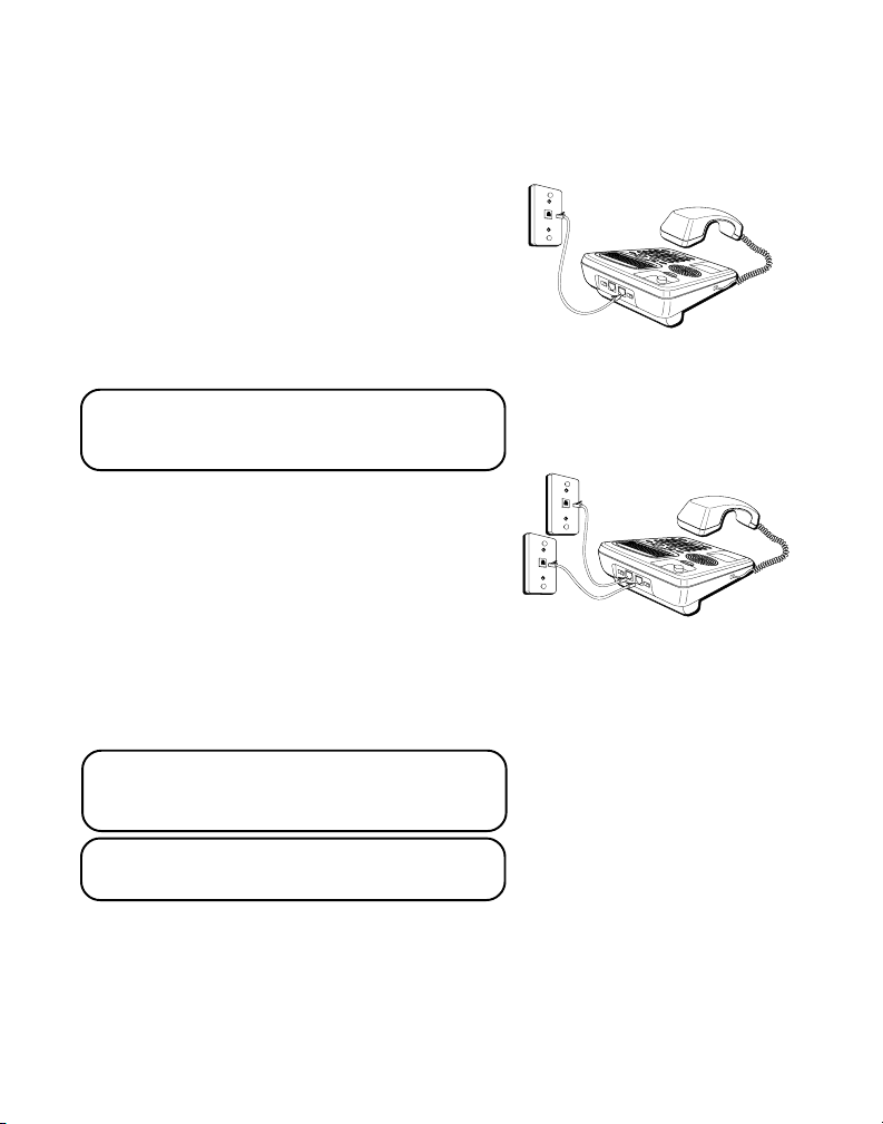
TWO LINES ON ASINGLE MODULAR JACK
The most common two-line phone system
uses a single RJ14 modular phone jack
which contains both phone lines.
NOTE: The Line 2 jack may be used as a
Data Port to connect your Fax, Modem,
Answerer or Cordless Phone to Line 2.
TWO LINES ON SEPARATE MODULAR
JACKS
If you have two separate modular phone
jacks each with its own line plug the grey
straight cord into the LINE 1 + 2 jack
located on the back of the base. Plug the
white straight cord into LINE 2 jack then
plug the opposite end of each cord into the
modular RJ11C phone jacks.
NOTE: Connect the telephone line cord
from LINE 1 + 2 jack into the outlet that
you want to be line 1.
NOTE: Two-line capability requires two line
service from your local telephone company.

8
INSTALLATION
FIGURE 1 FIGURE 2
Cord from
LINE 1+2 jack
Two single-line jacks (RJ11C)
Cord from
LINE 2 jack
GRAY WHITE
One dual-line jack
(RJ14C)
Cord from
LINE 1+2 jack
WHITE
1
DESKTOP INSTALLATION
A coiled handset cord and two straight telephone line cords are packaged
with your unit. Your two-line phone should be placed on a level surface
such as a tabletop or desk.
1. (See Figure 1) If you have one ual-line phone jack (RJ14C).
Plug one end of the white straight telephone line cord into the jack
marked LINE 1+2 on the back of the base and the other end into the
dual-line modular phone jack.
(See Figure 2) or if you have two single-line phone jack (RJ11C).
Plug one end of the grey straight telephone line cord into the jack
marked LINE 1+2 on the back of the base. Plug the white straight line
telephone cord into the jack marked LINE 2 on the back of the base. Then
plug the other end of each telephone line cord into the two single line
modular phone jacks.
9
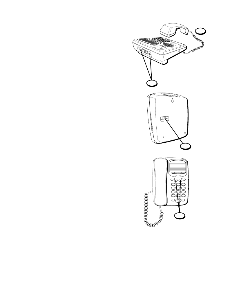
2.Plug one end of the coiled handset cord
into the handset and the opposite end
into the base.
3. Set the RINGER 1 and RINGER 2 volume
switches located at the back of the base
to the desired loudness.
• HI = Default loudest sound.
• LO = Sound will be the lowest.
• OFF = Telephone will not ring.
4. Set the TONE/PULSE switch to TONE if
you have Touch-Tone service or to PULSE
if you have rotary service.
5. Press the Line 1 button if the Line 1
telephone cord is connected. Otherwise
press the Line 2 button.
6. The unit is properly installed if you pick
up the handset and hear the dial tone.
Otherwise recheck all installation steps.
2
3
4
CONFERENCE
ABC
2
DEF
3
1
JKL
5
MNO
6
GHI
4
TUV
8
WXYZ
9
PQRS
7
OPER
0#
TONE
*
FLASHREDIAL/PAUSE
LINEHOLD
2
1
ABC
STORE
ABC
STORE
DIAL
SPEAKER
5
10
WALL MOUNT INSTALLATION
The speakerphone can be mounted on a
wall plate (not included).
1. (See Figure 1 on page 8) If you have one
ual-line phone jack (RJ14C).
Plug one end of the white straight line
cord into the jack marked LINE 1+2 on
the base and the other end into the
modular phone jack.
(See Figure 2 on page 8) if you have two
single-line phone jacks (RJ11C).
Plug one end of the grey straight
telephone line cord into the jack marked
LINE 1+2 on the back of the base. Plug
the white straight line telephone cord
into the jack marked LINE 2 on the back
of the base. Then plug the other end of
each telephone line cord into the two
single line modular phone jacks.
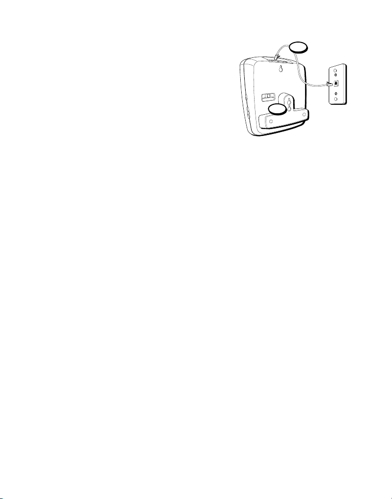
2. Turn the phone over and press down and
out on the top of the wall mounting
bracket. Lift the bracket off.
3. Reverse the wall mounting bracket so
that the thickest part is at the bottom of
the base.
4. Replace the wall mounting bracket by
inserting the top end in first and slide the
base down.
4
1
Table of contents
Languages:
Other GE Telephone manuals


