GE Albeo ABR2 User manual

ALB019
Albeo®ABR2 LED Luminaire
Heavy Industrial High Bay Lighting
BEFORE YOU BEGIN
Read these instructions completely and carefully.
Save these instructions for future use.
Installation Guide
ALB019
Risk of electrical shock. Turn power off before inspection, installation or
removal. Properly ground electrical enclosure.
Risk of re. Follow all NEC and local codes. Use only UL or IEC approved
wire for input/output connections. Minimum size 18 AWG.
This device complies with Part 15 of the FCC Rules. Operation is subject to the following two conditions: (1) This device may not cause harmful interference,
and (2) this device must accept any interference received, including interference that may cause undesired operation. CAN ICES-005 (A) / NMB-005 (A)
Note: This equipment has been tested and found to comply with the limits for a Class A digital device, pursuant to part 15 of the FCC Rules. These limits are
designed to provide reasonable protection against harmful interference when the equipment is operated in a commercial environment. This equipment
generates, uses, and can radiate radio frequency energy and, if not installed and used in accordance with the instruction manual, may cause harmful
interference to radio communications. Operation of this equipment in a residential area is likely to cause harmful interference in which case the user will be
required to correct the interference at his own expense.
Risgues de décharges électriques.
Coupez l’alimentation avant d’inspecter,
installer ou déplacer le luminaire. Assurez-vous de correctement mettre à
la terre le boîtier d’alimentation électrique.
Risque d’incendie. Respectez tous les codes NEC et codes locaux.
N’utilisez que des ls approuvés par UL ou IEC pour les entrées/sorties de
connexion. Taille minimum 18 AWG.
WARNING/AVERTISSEMENT/ADVERTENCIA
Save These Instructions
Use only in the manner intended by the manufacturer.
If you have any questions, contact the manufacturer.
Prepare Electrical Wiring
Electrical Requirements
The LED driver must be supplied with 120-277 VAC or 347/480
VAC, 50/60 Hz per productlabel and connected to an individual
properlygrounded branch circuit, protected by a 15 or 20ampere
circuit breaker.
Grounding Instructions
The grounding and bonding of the overall system shall be done
in accordance with National Electric Code (NEC) Article 600 and
local codes.

Installation GuideAlbeo®ABR2 LED Luminaire
Carefully unpack unit and properly inspect
for defects before installing. Wear work
gloves to prevent dirt and oil from being
transferred to the luminaire.
Provide at least 12” of clearance from the top of the xture to any ceiling or surface above.
NOTE: The standard conguration uses a 3-conductor SOOW cable. The dimming option utilizes a 5-conductor SOOW cable for both AC
and 0-10V control wires.
NOTE: For applications requiring the “R” corrosion resistant nish, use mounting hardware appropriate for the environment.
Please follow all UL, NEC and minimum load rating guidelines when selecting and installing a cable or chain.
NOTE: When selecting chain, a joint in a circular chain link shall be welded. A joint in a chain link of another shape shall not be located
within 30 degrees of the vertical unless welded.
Hang two chains/cables from a structural member of the ceiling. Fixture must be supported independently of an outlet box. Loop chain/
cable through the mounting slots next to each xture end. Chain/cable mounting locations must be in the slots at the ends of the xture.
Secure two 1/2” threaded rods into structural members in ceiling. Place a nut on each threaded rod where xture should hang. Slide rod
mount brackets onto threaded rods and tighten second nut onto rods to secure xture.
NOTE: Safety chains can be used in mounting slots at end of xture.
A
Section 1: Unit Installation
Section 2: Chain or Cable Mounting
Section 3: Threaded Rod Mounting
Choose a mounting method: chain or cable,
rod mount, or pendant mount.
Wire colors:
BC
Fixture Weight
ABR2-Series Max. Weight (lbs.)
120/277VConfiguration 347/480V
Single 21 23
Dual 45 49
BlackLive
White Neutral
Green Safety Ground
Purple0-10V (+)
Gray 0-10V (–)
Fixture Weight
ABR1-Series Max. Weight (lbs.)
120/277VConfiguration 347/480V
Single 21 23
Dual 45 49
BlackLive
White Neutral
Green Safety Ground
Purple0-10V (+)
Gray 0-10V (–)
Dual FixtureSingle Fixture
Attach to
structural
member
Fasten
with nuts
Attach to
structural
member
Attach to
structural
member
Single Fixture
See Note See Note
Dual Fixture
Dual FixtureSingle Fixture
Attach to
structural
member
Fasten
with nuts
Attach to
structural
member
Attach to
structural
member
Single Fixture
See Note See Note
Dual Fixture
2
Installation GuideAlbeo®ABR2 LED Luminaire
Section 4: Pendant Mounting
AC power cord
Tighten
screw
Black To AC Main
White
Green
Purple (+)
Gray (-)
Line
Neutral
Ground
0-10V(+)
0-10V(-)
To 0-10V
Dimmer
LED Driver
AC power cord
Tighten
screw
Black To AC Main
White
Green
Purple (+)
Gray (-)
Line
Neutral
Ground
0-10V(+)
0-10V(-)
To 0-10V
Dimmer
LED Driver
AC power cord
Tighten
screw
Black To AC Main
White
Green
Purple (+)
Gray (-)
Line
Neutral
Ground
0-10V(+)
0-10V(-)
To 0-10V
Dimmer
LED Driver
AC power cord
Tighten
screw
Black To AC Main
White
Green
Purple (+)
Gray (-)
Line
Neutral
Ground
0-10V(+)
0-10V(-)
To 0-10V
Dimmer
LED Driver
AC power cord
Tighten
screw
Black To AC Main
White
Green
Purple (+)
Gray (-)
Line
Neutral
Ground
0-10V(+)
0-10V(-)
To 0-10V
Dimmer
LED Driver
AC power cord
Tighten
screw
Black To AC Main
White
Green
Purple (+)
Gray (-)
Line
Neutral
Ground
0-10V(+)
0-10V(-)
To 0-10V
Dimmer
LED Driver
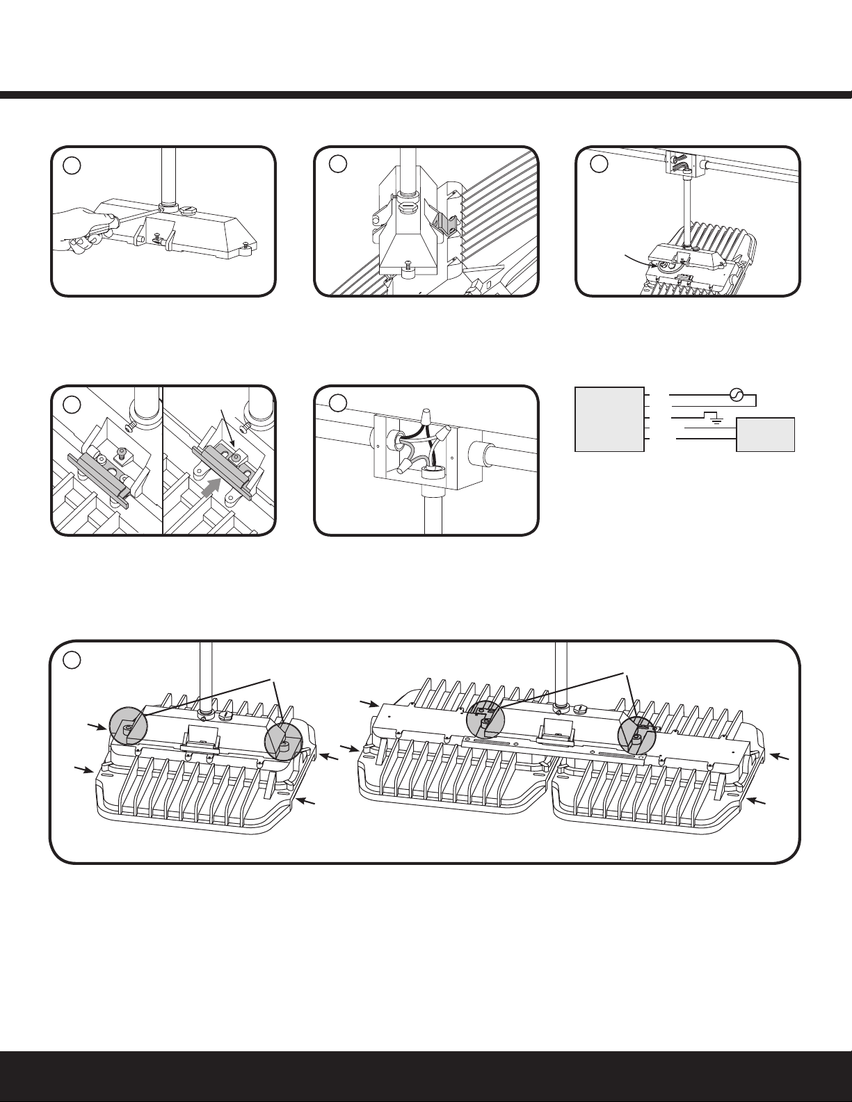
Attach pendant mount box to ¾” NPT
conduit.Determine rotation of xture
and lock orientation in place with provided
set screw.
Swing xture closed and secure with the
slide clip. Lock slide clip in place with screw.
Secure pendant mount box to xture by fully tightening the captive screws on the sides of the pendant mount box to the xture.
NOTE: Safety chains can be used in mounting slots at end of xture.
A
D
Single Fixtur
eD
ual Fixture
See
Note
See
Note
Captive screws Captive screws
3”
12”
1/2” bolts
Safety chain
F
Lift xture up and hang on pendant mount
box using hinge piece.
Connect the green (ground), black (line)
and white (neutral) wires of the AC line to
the similarly colored wires of the xture’s
power cord using UL listed wire connectors.
Close junction box.
Feed the AC power cord through the
conduit and into the junction box.
The 0-10V dimming option uses a 5-conductor
SOOW cable. Install cable per NEC and local
codes. For pendant mount option, cord can
be run through 1/2” NPT hole on top of the
mount box.
A 10V signal corresponds to 100% lumen
output. A 0V signal corresponds to ~10%
lumen output. Shorting the dimming wires
dims the xture to ~10% lumen output.
B
E
C
3

Installation GuideAlbeo®ABR2 LED Luminaire
Single FixtureDual Fixture
See
Note
See
Note
Captive screws Captive screws
3”
12”
1/2” bolts
Safety chain
Single FixtureDual Fixture
See
Note
See
Note
Captive screws Captive screws
3”
12”
1/2” bolts
Safety chain
Single FixtureDual Fixture
See
Note
See
Note
Captive screws Captive screws
3”
12”
1/2” bolts
Safety chain
Single FixtureDual Fixture
See
Note
See
Note
Captive screws Captive screws
3”
12”
1/2” bolts
Safety chain
Mount U-bracket to a at wall or ceiling
surface using (2) 1/2” bolts. Use either the 3”
or the 12” hole pattern.
Section 5: Rotatable Bracket Mounting
Section 6: Rotational Bracket Clearances
A
Lift xture up and insert provided (2) 1/4”
hex drive bolts through brackets, then
install provided locknuts.
Determine rotation of xture and lock
orientation in place (both sides) with
provided (2) 1/8” hex drive screws.
NOTE: Optional safety chains can be used
in 3/8” holes in sides of bracket and in the
mounting slots at the end of xture.
BC
D
NOTE: Luminaire not to be directly facing the mounting surface nor within 45° of each
direction.
NOTE: The rotatable bracket requires a 5°C maximum ambient temperature derating.
10.9 in.
10.8 in.
15.5 in.
21.7 in.
4

Installation GuideAlbeo®ABR2 LED Luminaire
These instructions do not purport to cover all details or variations in equipment nor to provide for every possible contingency to be met in connection with installation,
operation or maintenance. Should further information be desired or should particular problems arise which are not covered sufciently for the purchaser’s purposes, the
matter should be referred to GE current.
Ces instructions ne prétendent pas couvrir tous les détails ou variantes de l’équipement ni couvrir toutes les conditions possibles à satisfaire en rapport avec l’installation,
l’opération ou l’entretien. Si des informations supplémentaires sont souhaitées sur des aspects qui ne sont pas sufsamment couverts pour satisfaire les besoins du client, ou si
des problèmes particuliers se présentent, veuillez addresser ces questions à GE current.
Estas instrucciones no pretenden cubrir todos los detalles o variaciones en el equipo ni para prever cualquier contingencia que debe cumplir en relación con la instalación,
la operación o el mantenimiento. De ser deseada más información o se surgieran problemas particulares que no están cubiertos sucientemente para los propósitos del
comprador, favor de remitirse a GE current.
www.gecurrent.com
© 2020 Current Lighting Solutions, LLC. All rights reserved. GE and the GE monogram are trademarks of the
General Electric Company and are used under license. Information provided is subject to change without notice.
All values are design or typical values when measured under laboratory conditions.
ALB019 (Rev. 05/05/2020)
Questions:
Web: products.gecurrent.com
Phone: 1-866-855-8629
Section 7: Troubleshooting
Section 8: Maintenance
Symptom Solution
Luminaire will not •Check that the color of the supply side wires match the color of the wires they are connected to.
turn on. •Check that all wire connectors are properly connected.
•Verify that your input voltage is within specs.
•If you are using any additional controls (i.e. dimming wires, motion sensors), please also verify that those are
working properly and that the unit is setup to interface with the controllers.
•
Product should not be disassembled during installation process and/or while installed.
•
Lens should be cleaned periodically for maximum lumen output.
•
Inspect and clear any build-up on cooling ns periodically for maximum performance.
Table of contents
Other GE Lighting Equipment manuals

GE
GE NHL 23119LO User manual

GE
GE LED7-C7-50 User manual

GE
GE 73007 User manual

GE
GE Tetra GEPS24-300U-GL User manual

GE
GE Arize Element Series User manual

GE
GE ProSys DEH40212 User manual

GE
GE Versaflood II User manual

GE
GE Tetra PowerStrip DS User manual

GE
GE current Tetra miniMAX GEMM71-W1 User manual

GE
GE Current Tetra Slim EdgeStrip Series User manual


 User manual")

Popular Lighting Equipment manuals by other brands


Qazqa
Qazqa Suplux SL 3 Black 103062 instruction manual

Commercial Electric
Commercial Electric 54568141 Use and care guide

CREE LIGHTING
CREE LIGHTING 304 Series installation instructions

Goobay
Goobay 49867 user manual

ECOMAN ITALIA
ECOMAN ITALIA LED T8 instruction manual

Alkalite
Alkalite Krypton KT-81 user manual


