GE Digital Answer-Phone 2-9827 User manual

We bring good things to life.
2-9827
Digital Answer-Phone™
User’s Guide
US COVER E 0 4/3/97, 2:46 PM1
To Press
Play message .............................................. 1
Repeat message......................................... 8
(during playback)
Play previous message............................. 7
(during playback)
Stop ............................................................... 3
(during playback)
Erase message ........................................... 0
(during playback)
Skip message .............................................. 9
(during playback)
Turn answer OFF ........................................ 5
Turn answer ON ......................................... 6
Record outgoing announcement ............ 8
(Start recording after the beep)
Leave a message ....................................... 7
Play outgoing announcement ................. 2
If unit answers on 10th ring:
Answerer is off — Enter security code to
automatically turn on answerer.
- or -
Memory is full — Enter security code; listen
to messages; reset answerer.
To Press
Play message .............................................. 1
Repeat message......................................... 8
(during playback)
Play previous message............................. 7
(during playback)
Stop ............................................................... 3
(during playback)
Erase message ........................................... 0
(during playback)
Skip message .............................................. 9
(during playback)
Turn answer OFF ........................................ 5
Turn answer ON ......................................... 6
Record outgoing announcement ............ 8
(Start recording after the beep)
Leave a message ....................................... 7
Play outgoing announcement ................. 2
If unit answers on 10th ring:
Answerer is off — Enter security code to
automatically turn on answerer.
- or -
Memory is full — Enter security code;
listen to messages; reset answerer.
343A6547-0001 (Rev. 1 E/S) — SH. 1 OF 48 MODEL 2-9740
US FO E 1 4/3/97, 2:46 PM1

To Press
Play message .............................................. 1
Repeat message......................................... 8
(during playback)
Play previous message............................. 7
(during playback)
Stop ............................................................... 3
(during playback)
Erase message ........................................... 0
(during playback)
Skip message .............................................. 9
(during playback)
Turn answer OFF ........................................ 5
Turn answer ON ......................................... 6
Record outgoing announcement ............ 8
(Start recording after the beep)
Leave a message ....................................... 7
Play outgoing announcement ................. 2
If unit answers on 10th ring:
Answerer is off — Enter security code to
automatically turn on answerer.
- or -
Memory is full — Enter security code; listen
to messages; reset answerer.
To Press
Play message .............................................. 1
Repeat message......................................... 8
(during playback)
Play previous message............................. 7
(during playback)
Stop ............................................................... 3
(during playback)
Erase message ........................................... 0
(during playback)
Skip message .............................................. 9
(during playback)
Turn answer OFF ........................................ 5
Turn answer ON ......................................... 6
Record outgoing announcement ............ 8
(Start recording after the beep)
Leave a message ....................................... 7
Play outgoing announcement ................. 2
If unit answers on 10th ring:
Answerer is off — Enter security code to
automatically turn on answerer.
- or -
Memory is full — Enter security code;
listen to messages; reset answerer.
US FO E 1 4/3/97, 2:46 PM2

FCC NUMBER IS LOCATED ONTHE CABINET BOTTOM
REN NUMBER IS LOCATED ONTHE CABINET BOTTOM
FCC REGISTRATION INFORMATION
Your GE telephone equipment is registered with the Federal Communications Commission and is in compliance with parts 15
and 68, FCC Rules and Regulations.
1Notification to the LocalTelephone Company
On the bottom of this equipment is a label indicating, among other information, the FCC Registration number and Ringer
Equivalence Number (REN) for the equipment.You must, upon request, provide this information to your telephone
company.
The REN is useful in determining the number of devices you may connect to your telephone line and still have all of these
devices ring when your telephone number is called. In most (but not all) areas, the sum of the RENs of all devices connected
to one line should not exceed 5. Tobe certain of the number of devices you may connect to your line as determined by the REN,
you should contact your local telephone company.
Notes
• This equipment may not be used on coin service provided by the telephone company.
• Party lines are subject to state tariffs, and therefore, you may not be able to use your own telephone equipment if you are
on a party line. Check with your local telephone company.
• Notice must be given to the telephone company upon permanent disconnection of your telephone from your line.
2Rights of the Telephone Company
Should your equipment cause trouble on your line which may harm the telephone network, the telephone company shall,
where practicable, notify you that temporary discontinuance of service may be required. Where prior notice is not
practicable and the circumstances warrant such action, the telephone company may temporarily discontinue service
immediately. In case of such temporary discontinuance, the telephone company must: (1) promptly notify you of such
temporary discontinuance; (2) afford you the opportunity to correct the situation; and (3) inform you of your right to bring a
complaint to the Commission pursuant to procedures set forth in Subpart E of Part 68, FCC Rules and Regulations.
The telephone company may make changes in its communications facilities, equipment, operations of procedures where
such action is required in the operation of its business and not inconsistent with FCC Rules and Regulations. If these
changes are expected to affect the use or performance of your telephone equipment, thetelephone company must give you
adequate notice, in writing, to allow you to maintain uninterrupted service.
INTERFERENCE INFORMATION
This device complies with Part 15 of the FCC Rules. Operation is subject to the following two conditions: (1) This device may not
cause harmful interference; and (2) This device must accept any interference received, including interference that may cause
undesired operation.
This equipment has been tested and found to comply with the limits for a Class B digital device, pursuant to Part 15 of the FCC
Rules. These limits are designed to provide reasonable protection against harmful interference in a residential installation.
This equipment generates, uses, and can radiate radio frequency energy and, if not installed and used in accordance with the
instructions, may cause harmful interference to radio communications. However, there is no guarantee that interference will not
occur in a particular installation.
If this equipment does cause harmful interference to radio or television reception, which can be determined by turning the
equipment off and on, the user is encouraged to try to correct the interference by one or more of the following measures:
• Reorient or relocate the receiving antenna (that is, the antenna for radio or television that is “receiving” the interference).
• Reorient or relocate and increase the separation between the telecommunications equipment and receiving antenna.
• Connect the telecommunications equipment into an outlet on a circuit different from that to which the receiving antenna is
connected.
• Consult the dealer or an experienced radio/TV technician for help.
If these measures do not eliminate the interference, please consult your dealer or an experienced radio/television
technician for additional suggestions. Also, the Federal Communications Commission has prepared a helpful booklet,
“HowTo Identify and Resolve Radio/TV Interference Problems.”This booklet is available from the U.S. Government
Printing Office, Washington, D.C. 20402. Please specify stock number 004-000-00345-4 when ordering copies.
HEARING AID COMPATIBILITY
This telephone system meets FCC standards for Hearing Aid Compatiblility.
US COVER E 0 4/3/97, 2:46 PM2

INTRODUCTION
Your GE Digital Answer-Phone™ is designed to give you flexibility in use, and
high quality performance.To get the most from your new telephone, we suggest
that you take a few minutes right now to read through this instruction manual. If
you have any questions or problems, consult theTable of Contents, theTrouble-
shooting Guide, or the Index for the solution.
WARNING:
TO PREVENT FIRE
OR ELECTRICAL SHOCK HAZARD,
DO NOT EXPOSE THIS PRODUCT
TO RAIN OR MOISTURE.
SEE MARKING ON BOTTOM / BACK OF PRODUCT
CAUTION
RISKOFELECTRICSHOCK
DONOTOPEN
THE EXCLAMATION
POINT WITHIN THE
TRIANGLE IS A
WARNING SIGN
ALERTING YOU OF
IMPORTANT
INSTRUCTIONS
ACCOMPANYING
THE PRODUCT.
THE LIGHTNING
FLASH AND ARROW-
HEAD WITHIN THE
TRIANGLE IS A
WARNING SIGN
ALERTING YOU OF
"DANGEROUS
VOLTAGE" INSIDE
THE PRODUCT.
CAUTION: TO REDUCE THE
RISK OF ELECTRIC SHOCK,
DO NOT REMOVE COVER
(OR BACK). NO USER-
SERVICEABLE PARTS IN-
SIDE. REFER SERVICING
TO QUALIFIED SERVICE
PERSONNEL.
TABLE OF CONTENTS
INSTALLATION AND SETUP ................................................................................................................... 2
BEFORE YOU BEGIN ....................................................................................................................... 2
BATTERY INSTALLATION ................................................................................................................... 3
TABLETOP INSTALLATION ................................................................................................................. 4
WALL MOUNT INSTALLATION........................................................................................................... 5
BATTERY LOW INDICATOR................................................................................................................ 7
ANSWERING MACHINE SETUP ......................................................................................................... 7
RECORDING THE OUTGOING ANNOUNCEMENT .................................................................................... 8
TELEPHONE OPERATION ...................................................................................................................... 9
FLASH BUTTON ............................................................................................................................. 9
REDIAL BUTTON .......................................................................................................................... 10
TEMPORARY TONE FEATURE .......................................................................................................... 10
MEMORY DIALING ........................................................................................................................... 11
STORING ANUMBER IN MEMORY ................................................................................................... 11
DIALING ANUMBER FROM MEMORY ............................................................................................... 12
ANSWERING MACHINE OPERATION ..................................................................................................... 13
MESSAGE PLAYBACK ................................................................................................................... 13
ERASING MESSAGES DURING MESSAGE PLAYBACK .......................................................................... 13
LEAVING AMEMO ....................................................................................................................... 14
CALL SCREENING/AUTO DISCONNECT ............................................................................................. 14
TOLL SAVER FEATURE .................................................................................................................. 15
ACCESSING THE ANSWERER FROM ANOTHER LOCATION ...................................................................... 15
TROUBLESHOOTING TIPS ................................................................................................................... 16
CARE AND MAINTENANCE ................................................................................................................. 18
SERVICE ......................................................................................................................................... 18
INDEX ............................................................................................................................................ 19
LIMITED WARRANTY ......................................................................................................................... 20
US IB E 1 4/3/97, 2:46 PM1
2
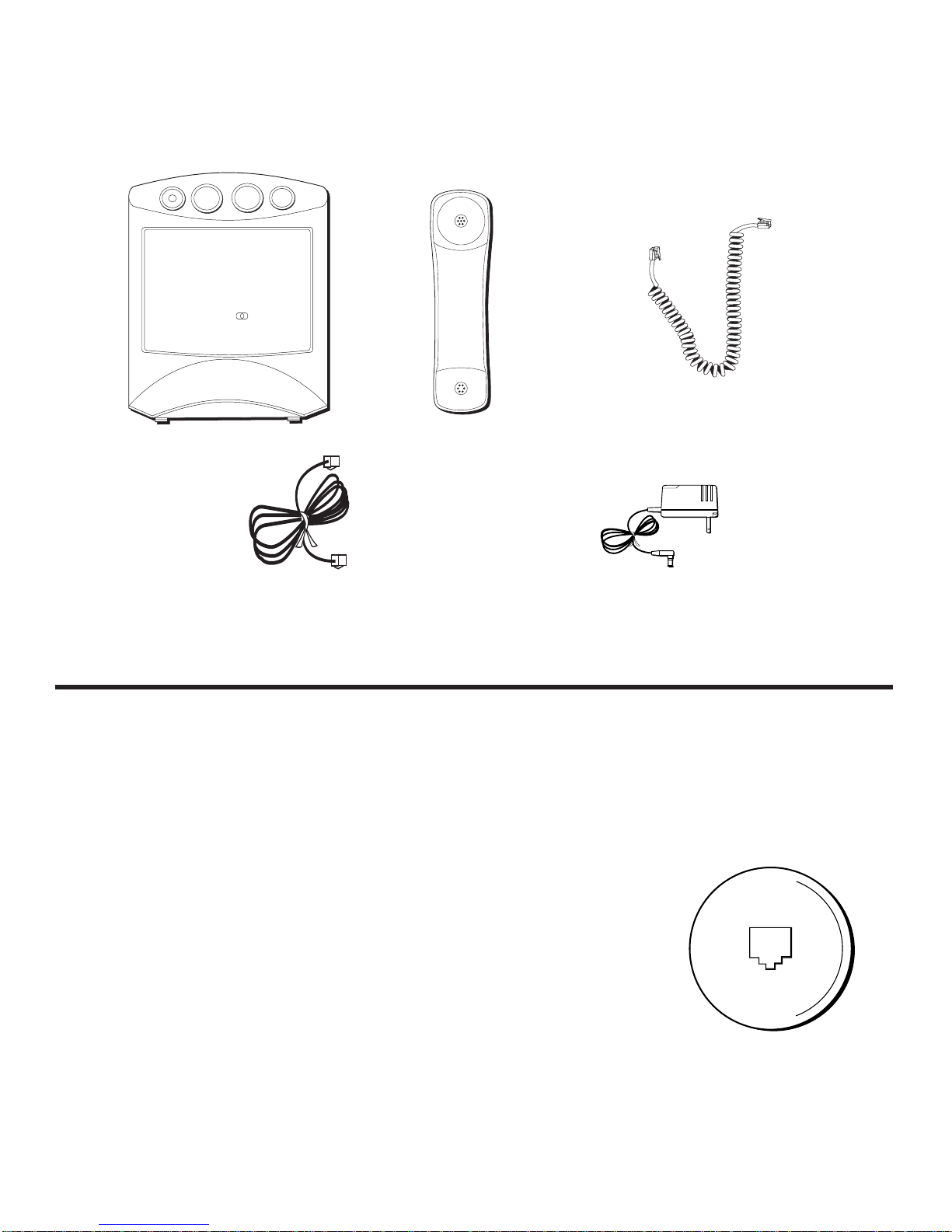
PARTS CHECKLIST
Your package should contain the following items:
Long handset cord
Base unit Handset
Phone line cord
INSTALLATION AND SETUP
Your GE Digital Answer-Phone™ can be mounted on the wall or placed on a
counter top or table top. After you decide which type of installation you want,
refer to the appropriate installation diagram.
BEFORE YOU BEGIN
2580059.12
AC power adapter
MODULAR JACK REQUIREMENTS
You need a USOC: RJ11C type modular jack, similar to
the one pictured here. If you don't have a modular
jack, call your phone company to find out how to get
one installed.
HOUR
MINUTE
WAKE
SLEEP
WAKE
AM
PM
FM
AM
MHZ
kHZ
88 • 92 • 96 • 100 • 104 • 108
550 • 650 • 800 • 1000 • 1300 • 1600
US IB E 1 4/3/97, 2:46 PM2
3
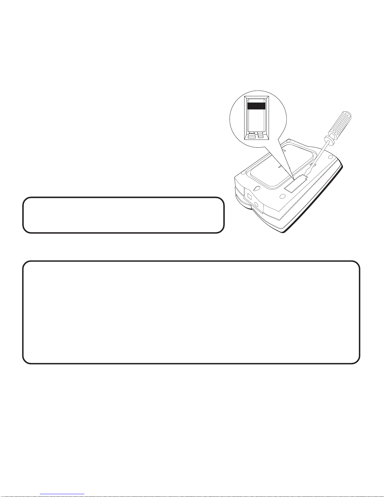
BATTERY INSTALLATION
In the event of a power loss, the 9-volt battery backup enables the answerer to
retain messages stored in memory, the outgoing announcement, and time/day
information.
NOTE: When the battery needs to be replaced,
the BATT. LOW indicator will flash.
BATTERY SAFETY PRECAUTIONS
For your safety, please follow these precautions:
• Do not recharge, disassemble, mutilate, wet, or dispose of batteries in fire.
• Keep batteries out of reach of children.
• Replace with 9V battery only (not included).
• When replacing batteries, be sure to unplug the phone line from the unit
before inserting the batteries.
BATTERY
1. Open the battery compartment door
with a flat tool.
2. Insert a 9V battery (not included), as
shown on the diagram inside the
battery compartment.
3. Close the battery compartment door.
US IB E 1 4/3/97, 2:46 PM3

4
TABLETOP INSTALLATION
NOTE: Make sure that you have inserted the battery before installing the
phone. If you have not, see p. 3 for battery installation information.
NOTE: Only use the Thomson 5-2399 AC adapter that came with this unit.
Using other adapters may damage the unit.
2
6
1
1. Plug the telephone line cord into PHONE LINE jack on the back of the unit
and the other end into a modular jack RJ11C .
2. Plug the handset cord into the handset and into the telephone jack on the
left side of the unit.
3. Set the PULSE/TONE switch on the left side of the phone to TONE if you use
touch-tone service; set it to PULSE if you have rotary service.
4. Adjust the RINGER volume switch on the left side of the phone to the
desired setting (the phone will only ring with the ringer set to LO or HI).
5. Adjust the ANSWERER volume switch on the right side of the phone to the
desired setting.
6. Plug the AC power adapter into the phone and into an AC outlet.
PULSE/TONE switch
RINGER volume switch
ANSWERER
volume switch
US IB E 1 4/3/97, 2:46 PM4
5
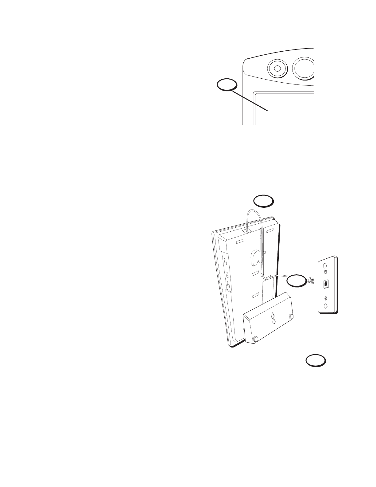
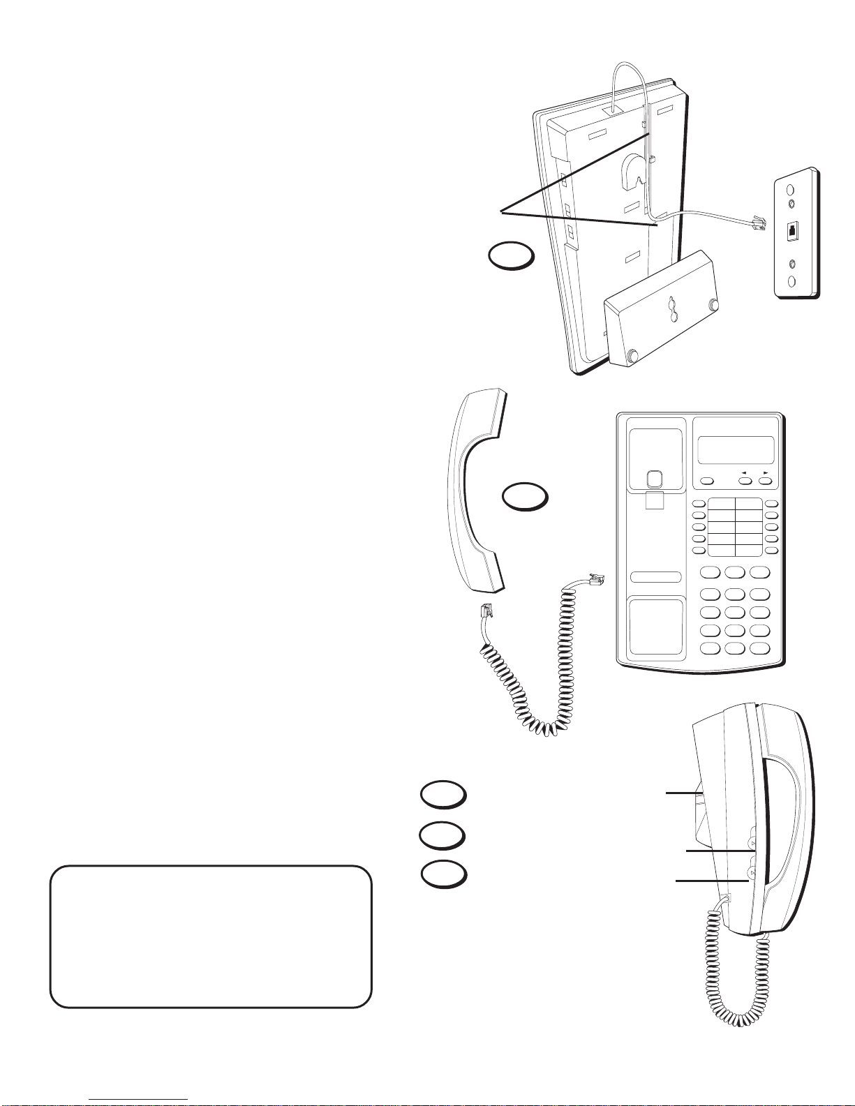
WALL MOUNT INSTALLATION
Your phone can be mounted on a wall
phone plate (not included).
1. Rotate the handset hook one-half turn.
4. Plug the AC adapter into the back of
the phone and into an AC outlet.
1
WAKE
SLEEP
AM
2
3
4
3. Attach the wall mount bracket by
turning theT-shaped bracket upside
down, as pictured. Then put the tabs
at the bottom of the bracket into the
matching slots near the bottom of the
unit and snap the top tab into place.
2. Plug one end of the telephone line
cord into the jack marked PHONE LINE
on the back of the unit. Wrap the
excess cord around the plastic tabs.
Plug the other end of the telephone
line cord into a modular wall jack.
US IB E 1 4/3/97, 2:46 PM5
6
5. Slip the mounting holes over
the wall plate posts and slide
the unit down firmly into
place.
6. Plug one end of the handset
cord into the handset and the
other end into the unit. Hang
up the phone.
7. Set the PULSE/TONE switch
on the left side of the phone
to TONE if you use touch-tone
service; set it to PULSE if you
have rotary service.
Mounting holes
5
FLASH REDIAL
2
ABC
3
DEF
1
5
JKL
6
MNO
4
GHI
8
TUV
9
WXY
7
PRS
0
OPER
#
*
STORE
DELETE REVIEW
6
8. Adjust the RINGER volume
switch on the left side of the
phone to the desired setting
(the phone will only ring with
the ringer set to LO or HI).
9. Adjust the ANSWERER
volume switch on the right
side of the phone to the
desired setting.
NOTE: Make sure that you have
inserted the battery before
installing the phone. If you have
not, see p. 3 for battery installa-
tion information.
RINGER
OFF LO HI
PULSE TONE
ANSWERER volume
switch (right side)
RINGER volume switch
PULSE/TONE switch
7
8
9
US IB E 1 4/3/97, 2:46 PM6
Table of contents
Other GE Answering Machine manuals


Popular Answering Machine manuals by other brands

Radio Shack
Radio Shack TAD-795 owner's manual

AT&T
AT&T 2455 user manual

Panasonic
Panasonic KX-TG2583CB operating instructions

Panasonic
Panasonic KX-TGE820E operating instructions

BellSouth
BellSouth GH9488 Owner's manual installation and operating instructions

Panasonic
Panasonic KX-TG2631 operating instructions


