Ganz ZP-EPC10 User manual
Installation Guide
Protocol converter
ZP-EPC10
Always read this manual before installing,
starting up, operating, storing or otherwise handling any part of the system.

This installation guide, edition 01 – 05/2000, is valid for use with the
the ZP-EPC10 protocol converter (year 2000 version)

Contents
Introduction
Intended use 4
EU directives 4
Identification plate 4
Safety Measures
Danger by Electric Current 5
Installation 5
Repair and Maintenance 5
Product Description
Scope of supply 6
Recommended Accessories 6
Summary of features 6
Connections and Switches 7
Installation
Connections 8
Configuration 10
Switching on and off 12
Function test 12
Care and maintenance
Cleaning 13
Maintenance 13
Passing on, Waste Disposal 13
Appendix
Conversion table for hexadecimal addresses 14
Typical system configurations 15
Meaning of function keys 18
Troubleshooting 19
Technical data 19

4
ZP-EPC10
Introduction
This installation guide is designed for the use of persons concerned with the installation
and configuration of the protocol converter and any devices connected to it. Relevant
international, national and – if applicable – local electronic engineering standards should
be observed at all times.
Intended use
The ZP-EPC10 protocol converter is designed to provide an interface between the CEC
C328 matrix switcher and the dome cameras of the SMD series from CBC. The device
converts the data transfer between protocols RS422 and RS485. The unit is designed
exclusively for this function. No other application is permitted.
For further information on operating aspects that are not covered in this guide, please
contact us at:
CBC (Deutschland) GmbH
Hansaallee 191
D – 40549 Düsseldorf
Phone: +49 (0) 211 53 06 70
Fax: +49 (0) 211 53 06 71 80
EU directives
The ZP-EPC10 protocol converter fulfils the specifications of European Union directive
89/336 (covering electromagnetic compatibility).
Identification plate
Precise identification of each unit is provided by the plates attached to the front and rear
of the housing, which show the model designation and serial number. Keep these details
for reference, should you have questions or for ordering spare parts.
Model:
Serial Number:
Implementation
CBC (Europe) Ltd.
7/8, Garrick Industrial Centre, Irving Way
GB – London NW9 6AQ
Phone +44 (0) 181 732 3310
Fax +44 (0) 181 202 3387
ZP-EPC10
5
(05/2000)
Security Measures
Safety Measures
Danger by Electric Current
• The device must be connected to the appropriate power supply.
• Only use a suitable adaptor (see technical data).
• Disconnect the adaptor from the mains supply when an error occurs.
• Only use the adaptor and device in a dry, weather protected environment.
• If safe application of the device is no longer guaranteed, it should not be used but be
protected against inadvertent handling. Safe use is no longer possible, e.g.
– when the device or cables are visibly damaged,
– when the device does not work properly,
– when the device has been exposed to rain or wet conditions,
– when the item has been pierced,
– after prolonged storage in unfavourable conditions or after difficult transportation.
Have the device checked by CBC.
Installation
• When installing the device, electrical engineering regulations should be adhered to.
• Follow the instructions for installation and operation other equipment, e.g. cameras.
These instructions contain important advice on safety and approved use of equipment.
• Carefully follow guidelines for installation and use. Not doing this could lead to personal
injury, damage to property or to the equipment itself.
Repair and Maintenance
• Never open the housing of the protocol converter. The device does not contain parts
that you can repair or replace yourself.
• Ensure that repair or maintenance work is carried out by qualified personnel (electrical
engineers).

6
ZP-EPC10
Product Description
Scope of supply
❚Protocol converter ZP-EPC10
❚4 screw clamps
❚Installation guide
Recommended Accessories
❚CV12 power supply available from CBC
❚Cable made to Belden specifications
Summary of features
The ZP-EPC10 protocol converter is designed to convert control signals between
RS422 (full-duplex) and RS485 (half-duplex) protocol. In addition to adjusting for diffe-
rent pin assignments, the unit also converts the protocols used by the CEC C328 video
multiplexer and the SMD-type dome cameras manufactured by CBC. A single protocol
converter can support up to 31 dome cameras. It is also possible to cascade up to nine
protocol converters to control a maximum of 256 dome cameras using a single multi-
plexer.
Both SMD-type and CEC VSD-type dome cameras (only the former use RS485 proto-
col) may be operated jointly.
The following dome camera functions are supported:
❚Pan, tilt, zoom, focus, iris
❚Presets
❚Writing EEPROM
❚Start position (Home)
❚Auto-focus, auto-iris, manual iris control
❚Automatic pan or tilt function between presets 1 and 2
❚Control of pan and tilt speed
❚Camera speed control
☞Note:
Observe the examples and explanations given from page 15 onwards.
Product Description

ZP-EPC10
7
(05/2000)
Product Description
1POWER light
Lights up red when ready
2ADDRESSING rotary switch
Adjustment to start address
(hexadecimal in value)
3ADDRESSING rotary switch
Adjustment to end address
(hexadecimal in value)
4OPTIONS switches
Reserved for further extensions
5POWER clamp socket
To connect the adaptor
6DOME clamp socket
To link up the control line for the
dome cameras
7TERM switches
To terminate the data chain
8CPU clamp socket
For connection of the
CEC C328 matrix switcher
9RCVRS clamp socket
For connection of further receivers
(e.g. CEC VSD dome cameras) or
ZP-EPC10 converters
Connections and Switches
8
ZP-EPC10
Installation
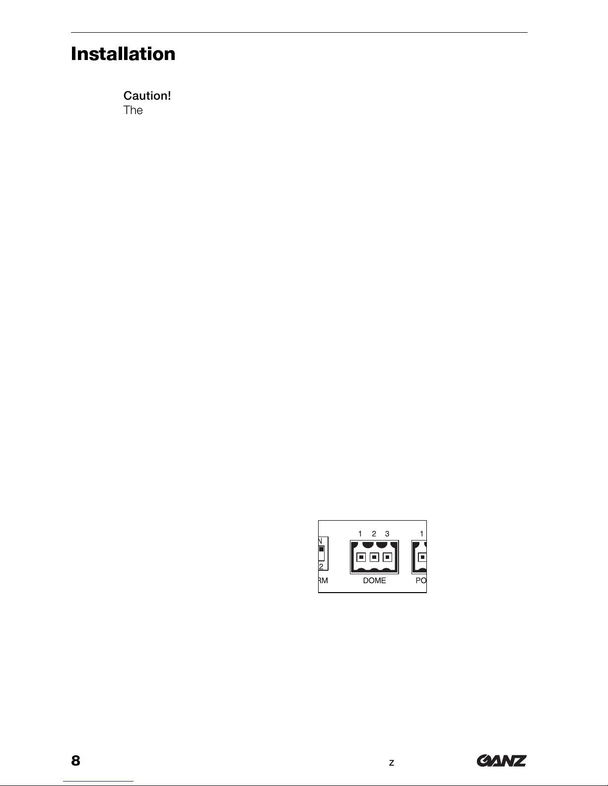
zCaution!
The device is intended for indoor use. Do not expose it to either extreme tem-
peratures or extreme humidity at any time and choose its setup site accord-
ingly. The ambient temperature must fall within the range from 5 to 40 °C at all
times, the relative humidity of the air must not exceed 90 %.
❚Do not set up the device in the immediate vicinity of radiators or other heat sources.
Avoid sites which are exposed to direct sunlight.
❚Create sufficient space for lines and cables.
❚Ensure sufficient ventilation of the device.
❚For cable connections, use only cables which have been part of the delivery or are
otherwise suitable and which help to suppress electric interference.
❚When laying out the lines and cables, make sure that they cannot be easily damaged
and ease wherever possible tensile loads and stresses.
Connections
Dome cameras
Connect the dome cameras (maximum 31 cameras per converter) to the converter’s
DOME contacts.
Use Belden cables for connections if possible or twisted pair cables, based on the same
Belden standard.
Pin assignment DOME connector
1Ground
2 Signal –
3 Signal +
Matrix switcher and further receivers or converters
You can lock the protocol converter in place on its own or as one of several devices into
a RS422 bus on the CEC C328 matrix switcher. The order or position of each of the sin-
gle devices has no particular effect because each device has its own address within the
bus system.
Installation

ZP-EPC10
9
(05/2000)
Installation
When the device is switched off, internal relays produce direct connections between
Command (Input) and Command (Output), as in between Answer (Input) and Answer
(Output) so that the signals are transmitted transparent between the remaining devices.
Use Belden cables for connections if possible or twisted pair cables, based on the same
Belden standard.
• Connect the CPU contacts with the RCVRS (J4) connection of the matrix switcher
when connecting the protocol converter directly to the matrix switcher.
• When positioning the converter anywhere in the RS422 chain, connect the CPU
contacts to the RCVRS contacts of the receiver or converter nearest to the matrix
switcher.
• Connect further RS422 receivers (e.g. CEC PTR or CEC VSD) or converters with
RCVRS contacts of the protocol converter.
Pin assignment CPU connector
1Ground
2Answer – (Output)
3Answer + (Output)
4Command – (Input)
5Command + (Input)
Pin assignment RCVRS connector
1Ground
2Command – (Output)
3Command + (Output)
4Answer – (Input)
5Answer + (Input)
Voltage supply
Use an adapter for voltage supply that supplies a DC voltage of between 9 and 24 volts.
The maximum power input corresponds to 200 mA.
Pin assignment POWER connector
1Positive
2Negative (ground)
10
ZP-EPC10
Configuration
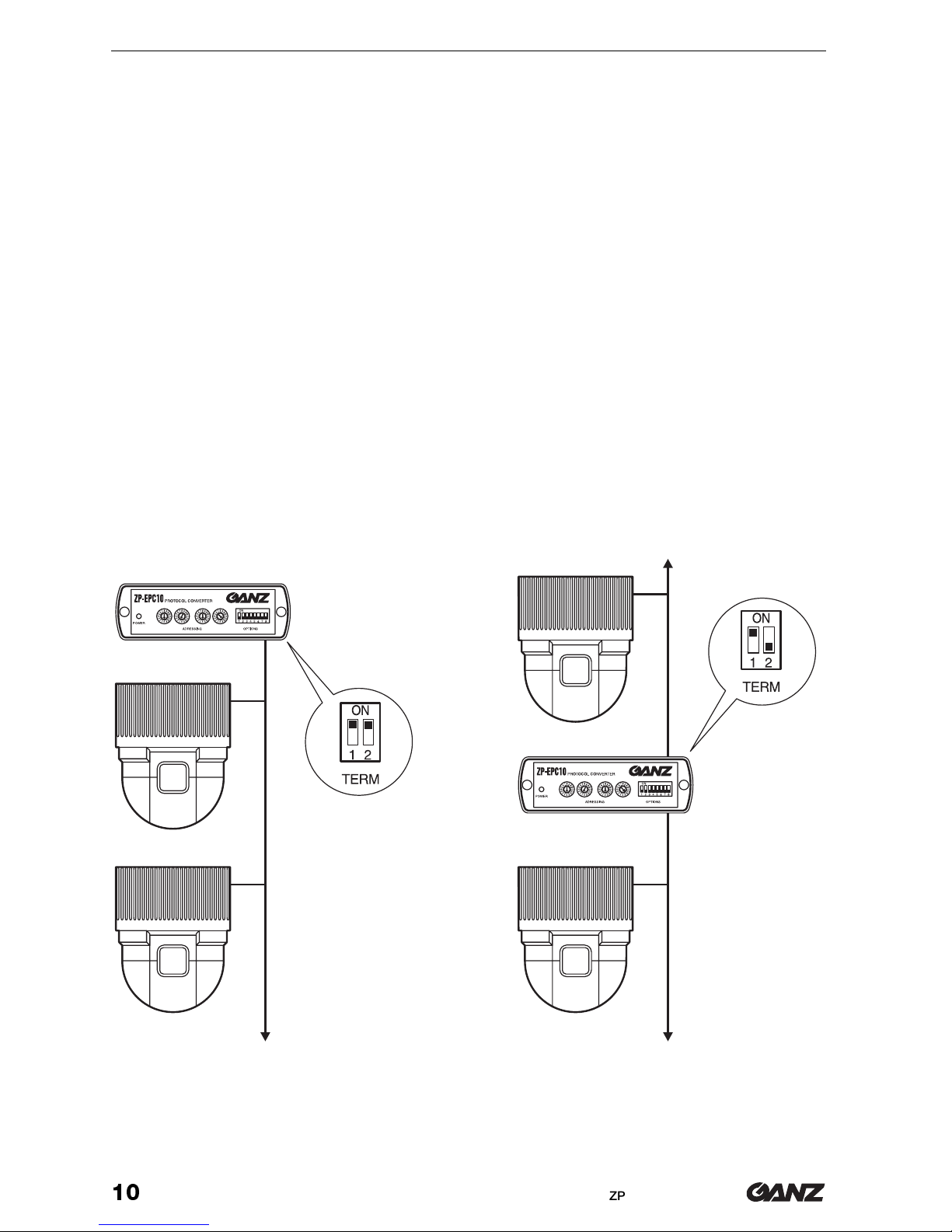
Termination
If you are using several units in a daisy chain configuration (RS422 or RS485), you must
terminate the end-connectors with a resistor equivalent to the cable impedance, otherwi-
se the system may not communicate properly.
The factory settings for the protocol converter are such that its RS422 connections are
already terminated. It is possible to bypass the terminal resistors, if you decide to chan-
ge your system to a different configuration in the future. Normally the TERM 1 switch
should be left in the ON position.
If the protocol converter is the first unit in the dome camera daisy chain (DOME connec-
tion), the TERM 2 switch must be in the ON position to terminate the daisy chain correct-
ly at this end. The last dome camera in the daisy chain should also have the terminal resi-
stor connected.
In an RS485 cascade, if cabling constraints make it impossible to connect the protocol
converter in the first position, then the TERM 2 switch should be in the OFF position
(down). The first and last dome camera in such a daisy chain must have their terminal re-
sistors connected.
Installation
Table of contents
Other Ganz Media Converter manuals

Ganz
Ganz ZN-S100AE User manual

Ganz
Ganz ZN-S1000V User manual

Ganz
Ganz ZA-NVE12K series User manual
Ganz
Ganz PixelPro GXi Series User manual

Ganz
Ganz ZN-S1000VE User manual
Ganz
Ganz PixelPro GXi Series User manual

Ganz
Ganz ZA-NVE40K User manual

Ganz
Ganz ZN-S100V User manual
Ganz
Ganz PixelPro ZS1-4DS User manual
Ganz
Ganz PixelPro GXi Series User manual


