G-Force SL 2000 DC2 Manual

1
SL 2000 DC2 SLIDING GATE MOTOR KIT
Solar Powered and 12V Low Voltage
Installation and Set Up Instructions
Unit 27 / 49 Corporate Boulevard Bayswater Vic 3153 Phone 1800 111 930
Email info@gforceautogates.com.au Web www.gforceautogates.com.au
© 2012 G Force Automac Gates All Rights Reserved

2
Important Safety Warnings
Please read these important safety warnings before attempting to install or use this product
Do not operate the gate motor unless the gates are in full view and free from objects such as
cars, children or people.
Children must be supervised near the gates at all times, especially when the gate motor is in
use.
Ensure that the obstruction sensing function of the gate motor is operational and adjusted
where necessary.
Keep hands and any loose clothing well clear of the gate(s) and gate motor at all times.
Disconnect the power from the mains before attempting to service the gate motor or removing
the cover.
Keep any gate controllers out of reach of children. Any wired or wireless controllers must be
installed away from any moving parts, and it must be at a minimum height of 1.5m from the
ground.
If the ‘Auto Close’ feature is enabled, then precautions should be taken to ensure the gate can
close without hitting any obstructions or suitable safety accessories are also installed.
This equipment is designed for use as a Sliding Gate Opening Device only. Do not attempt to
use for any other purpose as injury or property damage may occur.
Regularly check that all safety features and safety accessories are fully functioning.
Warning:
Failure to comply with these safety warnings or installation instructions may result in serious
personal injury and / or property damage.
Installation Checklist
Read all instructions and data sheets before installing the gate motor kit. Failure to follow the
instructions could void warranty.
The gate must to be in good operating condition. The gate needs to open and close freely for its
full length of travel and that it does not stick or bind on anything. The gate posts are correctly
and securely mounted
We recommend 1.5mm twin active lighting cable for power supply wiring and 1mm figure 8 wire
for wiring push buttons and other auxiliary items.
SL GATE MOTOR INSTALLATION
AND SET UP INSTRUCTIONS
© 2012 G Force Automac Gates All Rights Reserved

3
SL DC2 GATE MOTOR
INSTALLATION AND SET UP
INSTRUCTIONS
Motor cover
Solar Regulator (Only
installed in solar
powered gate
motors)
Drive Gear Limit
Switch
Spring
Circuit Board
Manual release
mechanism
Limit Switch
Assembly
Remote Receiver
Baery
Motor
Gate motor mounng foot
© 2012 G Force Automac Gates All Rights Reserved

4
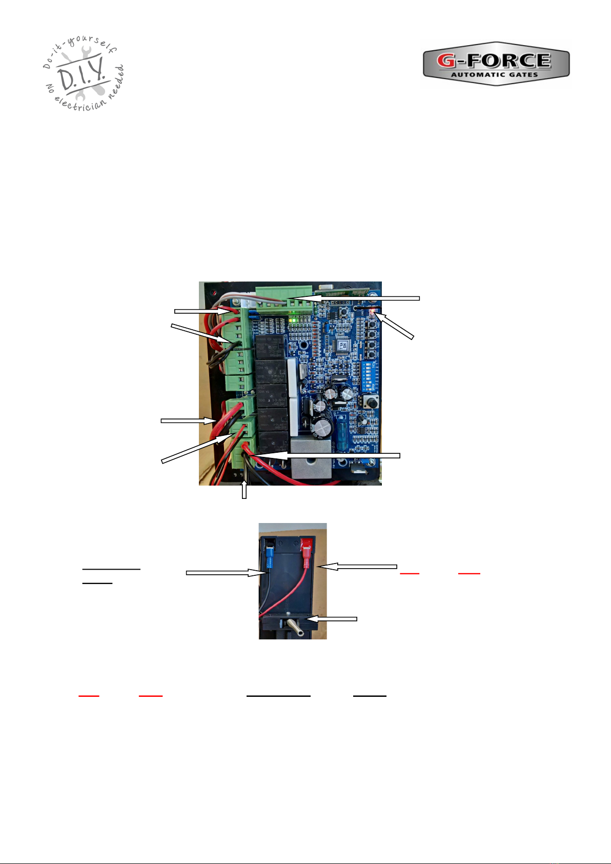
SL DC2 Circuit Board
Data Sheet DIY Automatic Gate Kits
Solar & Low Voltage Specialists
PH 1800 111 930
info@gforceautogates.com.au
www.gforceautogates.com.au
Auto Close Time
set push button
Gate Direction LED’s
Open GREEN LED
Close RED LED
12 - 24VAC
Transformer Terminals
Wire in Receiver / Push
Button Trigger Terminals
Connect wires to OSC and
COM
PE Beam Terminals
Connect wires to PEB
and COM
Power Out Connection
Terminals “V+”
positive terminal / “0V”
Negative terminal
Motor Force
Trim Pot
PE Beam Jumper
(Remove Jumper
when connecting
Safety Beams)
Battery leads RED
Positive / BLACK
Negative
Motor 1 Wire
Terminals
Limit Switch
Terminals
DIP Switches 1
and 8 for the
Auto Close
function
© 2012 G Force Automac Gates All Rights Reserved
CAUTION—DIP SWITCH 6 MUST
BE IN THE ‘ON’ POSITION

5
SL DC2 GATE MOTOR
INSTALLATION AND SET UP
INSTRUCTIONS
Mode of Gate Operation
The gate motor is supplied in MANUAL mode as standard.
Manual Release Mechanism
The manual release mechanism is located at the front of the motor. To access the manual
release mechanism you will need the key for the lock and the hex key that was supplied with the
SL gate motor kit to engage or release the clutch.
Manual Mode
Put the key in the keyhole and turn to the key in the “Open” direction as shown by the arrow on
the cover to open the hole for the hex key. Insert the hex key into the hole and turn it in the
“Open” direction until you can freely move the motor drive gear and / or gate freely by hand.
Automatic Mode
Insert the key in the keyhole and turn the key in the “Open” direction as shown by the arrow on
the cover to open the hole for the hex key. Insert the hex key into the hole and turn it in the
“Close” direction until it tightens and the motor drive gear is fully engaged and you can not rotate
the drive gear or move the gate freely by hand. Rock the drive gear or gate backwards and
forward the ensure the clutch is correctly engaged. Remove the hex key and turn the lock in the
“Close” direction and remove the lock key.
Manual Release
Mechanism
Lock
Keys Hex Key
Turn lock key to open / close
hole for hex key
Turn hex key open / close to
release / engage clutch
© 2012 G Force Automac Gates All Rights Reserved
6
Pre Installation set up and testing
Handset remote
receiver trigger
wires
Motor wires
Battery
Wires
Battery connection for bench testing
and set up
Limit switch
wires
SL DC2 GATE MOTOR
INSTALLATION AND SET UP
INSTRUCTIONS
Black / Blue wire to
Black battery
terminal
Red wire to Red bat-
tery terminal
Handset remote
receiver power
wires
Gate Direction LED’s
Open GREEN LED
Close RED LED
12 v Transformer Wires
© 2012 G Force Automac Gates All Rights Reserved
Refer to the “SL DC2 Circuit Board” data sheet included with this manual and locate battery connection
wires on the circuit board. Connect the battery wires to the battery terminals on the battery. Note the po-
larity (Red wire to Red battery terminal, Black / Blue wire to Black battery terminal). The board
should now be powered and great care should be taken to avoid shorting out or otherwise damaging the
circuit board. Green and Red gate direction LED”s will flash when power is connected.
Activate the gate motor using one of the handset remote. The remotes are coded to the gate motor dur-
ing assembly. Alternatively, refer to the “Handset Remote Programming” data sheet to code in the re-
motes. Press the remote again to stop the motor. Press the remote again to reverse the motor direction.
Disconnect the battery wires when finished.
We recommend the gate motor settings and direction of rotation be set up and tested prior to
installation.
Un pack the motor and remove the motor cover. Place the gate motor on a suitable work bench.
Visually inspect the motor to ensure nothing has moved during transit. Refer to the “SL DC2 Circuit
Board” data sheet included with this manual and familiarise yourself with the layout and location of the
items and wiring terminals

7
Pre Installation set up and
testing (continued)
Setting Motor Direction
Refer to the “SL DC2 Circuit Board” data sheet included with this manual and locate the direction
LED’s on the circuit board. The GREEN LED indicates opening direction and the RED LED
indicates closing direction.
Activate the gate motor using the handset remote and check the rotation of the drive gear is
turning in the correct direction for opening the gate and the GREEN LED light is on OR the
correct direction for closing the gate and the RED LED light is on.
If the motor is going in the wrong direction, disconnect all power. Refer to the “SL DC2 Circuit
Board” data sheet included with this manual and locate the ‘M1 Motor’ terminals. on the circuit
board. Swap the red and black motor wires connected to ‘M1 Motor terminals on the circuit
board. The red wire should be connected to the terminal that had the black wire connected to it
and the black wire should be connected to the terminal that had the red wire connected to it. This
will reverse the direction of the motor. Now locate the two RED limit switch wires and swap their
terminal positions around.
Activate the gate motor again using the handset remote and check the rotation of the drive gear
is turning in the correct direction for opening the gate and the GREEN LED light is on OR closing
the gate and the RED LED light is on.
RED Limit
Switch wires
Opening Direction
Green LED is on
Closing Direction
Red LED is on
Battery wires
M1 Motor terminals.
RED and Black wires.
© 2012 G Force Automac Gates All Rights Reserved
8
Mounting the Gate Motor / Gear Rack:
The gate motor should be mounted to the side of the driveway to provide clear passage of travel for
vehicles. The gate motor should be securely bolted down to a solid concrete pad or steel base frame. The
gate motor should be parallel to the gate and there should be no contact between the gate motor and the
gate frame. Ensure there is adequate space for removal of the motor cover and clear access to the
internal components of the gate motor and clear access to the external manual release mechanism.
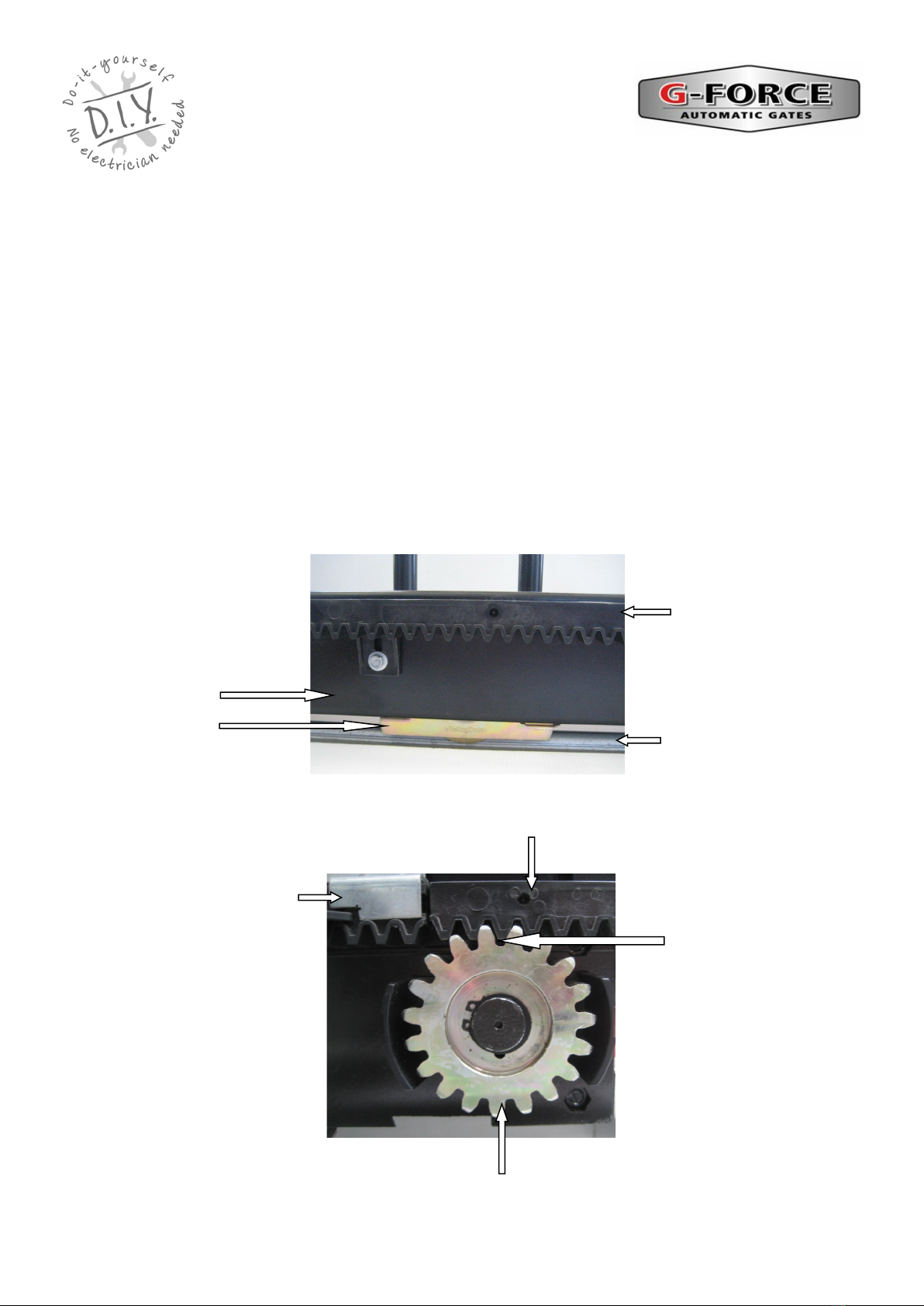
Mount the gear rack onto the gate at the required height to ensure correct engagement to the drive gear.
We suggest a gap of 2-3mm between rack and drive gear. Temporarily placing a 2-3 mm spacer under
the motor feet can help set the required height. Remove the spacer when finished.
To ensure smooth running of the gate, there should not be any space between the ends of each gear rack
section. Adjust the rack to the required height by running the gate back and forwards with the motor in
‘manual mode’. The gear rack can then be adjusted up or down as required to ensure the correct and
consistent gap. Ensure the rack does not hit, rub or contact any part of the motor cover or motor body.
2—3 mm Gap between
drive gear and gear rack
Limit Switch
Bracket
Gear Rack
Drive Gear
SL DC2 GATE MOTOR
INSTALLATION AND SET UP
INSTRUCTIONS
Gate Frame
Gate wheel Ground Track
Gear Rack
© 2012 G Force Automac Gates All Rights Reserved
9
SL DC2 GATE MOTOR
INSTALLATION AND SET UP
INSTRUCTIONS
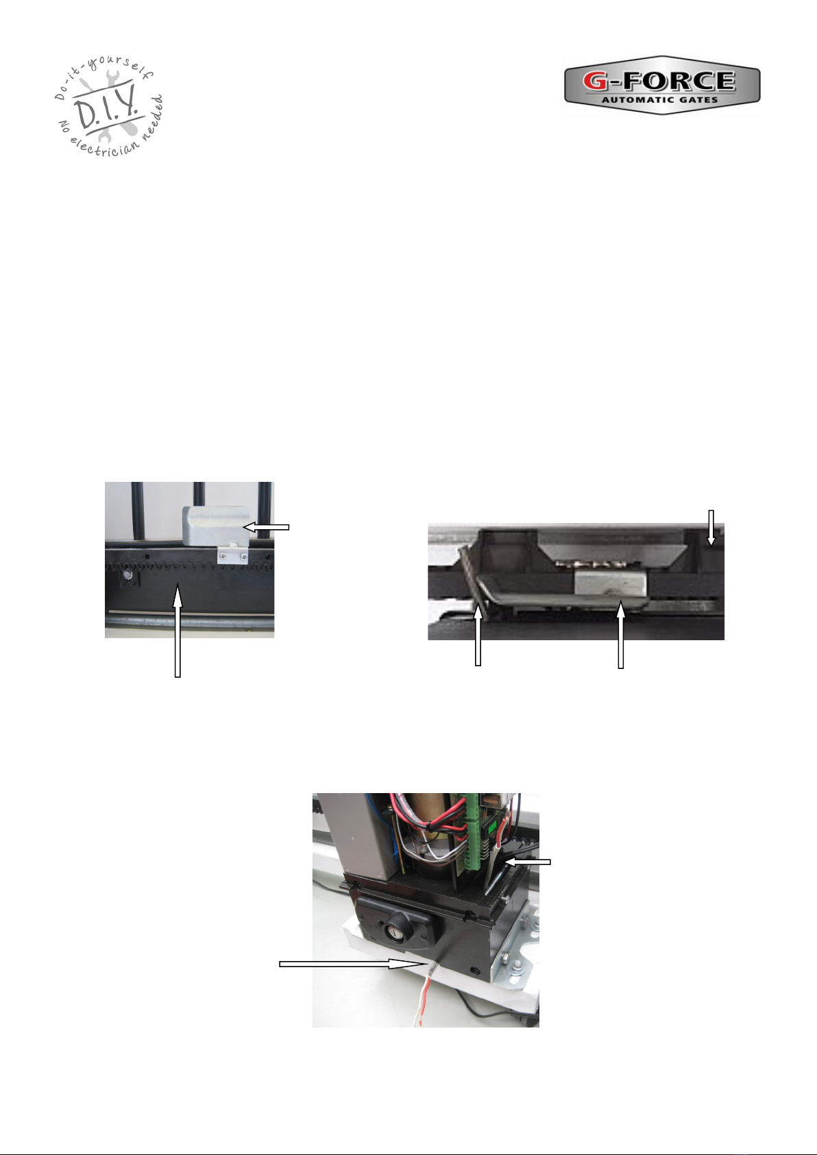
Mounting the Gate Motor / Limit Switch Brackets:
The limit switch brackets are mounted at either end of the gear rack to set the open and close positions of
the gate.
Put the gate motor into ‘manual mode’. Manually slide the gate into the fully closed position and then
open the gate 15 —25mm. Attach one limit switch bracket onto the rack so the end of the bracket just
touches the limit switch spring. Manually slide the gate at the fully open position and then close the gate
15 —25mm. Attach one limit switch bracket onto the rack so the end of the bracket just touches the limit
switch spring. In these positions, when the gate motor is operating, the limit switch brackets should push
against the limit switch spring to click the limit switch off (an audible sound can be heard when the
switching occurs).
Put the gate motor into ‘automatic mode’ and activate the gate motor to open and close the gate several
times to ensure the limit switch brackets are correctly positioned. Adjust the bracket position as required.
The gate should stop in the open and closed positions before making contact any end stops Ensure the
brackets and bracket screws do not hit, rub or contact any part of the motor cover or motor body.
Limit Switch Bracket
Limit Switch spring
Gear Rack
Limit Switch
Bracket
Gear Rack
POWER WIRE ENTRY
Power Wire external
entry
Power Wire Internal entry.
Drill a hole in the plasc insect
shield for the cable
© 2012 G Force Automac Gates All Rights Reserved
10
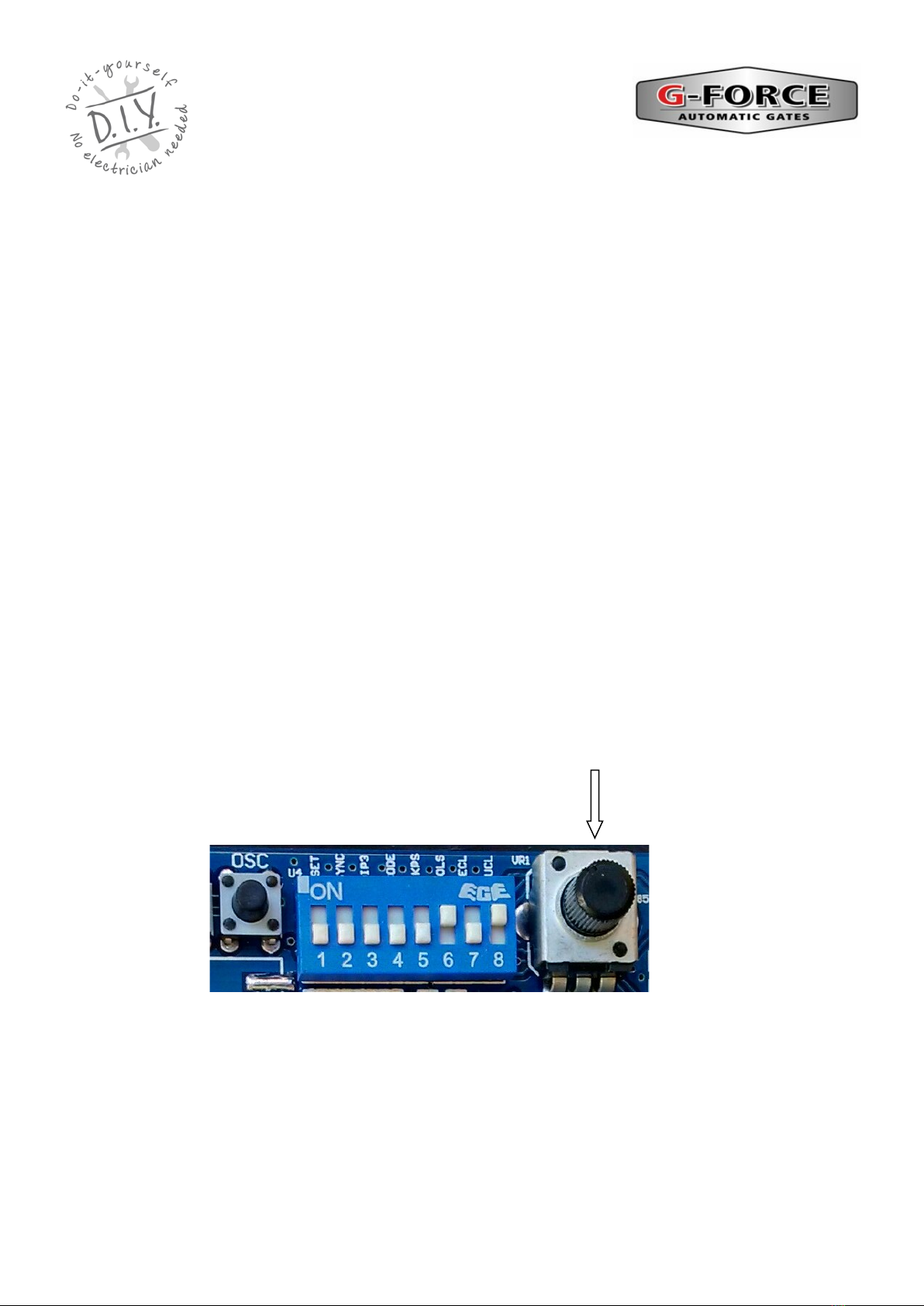
SL DC2 Circuit Board Adjustments
SL DC2 CONTROL BOARD
Motor Torque / Obstruction Sensing / Auto Reverse Adjustment
Refer to the “SL DC2 Circuit Board” data sheet included with this manual and locate the
‘FORCE’ trim pot on the circuit board.
This adjustment controls the motor torque and obstruction sensing of the gate motor. The motor
needs to have enough torque (force) to fully open and close the gate. However, the more torque
the motor has, the less obstruction sensitivity there is and therefore the gate may hit an obstruc-
tion more forcefully.
Usually the motor FORCE trim pot is set to the half way position however turn the FORCE trim
pot anti-clockwise (-) to increase sensitivity to an obstruction or turn the FORCE trim pot clock-
wise (+) to increase the motor torque (force) of the motor.
Motor Force Trim Pot
SL DC2 GATE MOTOR
INSTALLATION AND SET UP
INSTRUCTIONS
© 2012 G Force Automac Gates All Rights Reserved
Table of contents
Other G-Force Garage Door Opener manuals

Popular Garage Door Opener manuals by other brands


Craftsman
Craftsman 139.53924 owner's manual

Chamberlain
Chamberlain MyQ 940ESTD owner's manual

Automatic Technology
Automatic Technology GDO-9V1 SecuraLift installation instructions

Westfalia
Westfalia 19 36 07 instruction manual

Chamberlain
Chamberlain HD520EVP manual

Cardin
Cardin BL Series instruction manual