Fujitsu CFD5GRUDB3 User manual

4.6
Cable Installation
In this section:
4.6.1 Connect Frame Ground Cable
4.6.2 Connect eCPRI Optical Cable
4.6.3 Connect AISG Cables
4.6.4 Connect RF Cables
4.6.5 Connect DC –48 V Power Cable
e following sections describe how to connect all necessary cables to the RU.
Important: Do not use a cable that contains red phosphorus as a ame retardant. is may cause
problems, for example, heat generation and emiing smoke.
Important: Ensure the cable connector gland or clamp is the correct size for the selected cable
diameter to prevent water ingress.
4.6.1
Connect Frame Ground Cable
is procedure describes how to connect a Frame Ground (FG) cable to the RU.
Prerequisites:
■RU mounted and not powered up
■Available AWG ground cable with two hole lug (green or green with yellow stripe, 0.625 mm hole spacing)
■Weatherproong method to prevent moisture intrusion
■13 mm socket
■Philips screwdriver
Danger: Use properly insulated tools and perform all safety
precautions in accordance with local safety practices when working
on or around power terminals, power cables, and power connectors.
Contacting power terminals, uninsulated conductors, cable wiring,
or any connector that could be part of a live electrical circuit can
result in death or serious personal injury.
Danger: Utilisez des outils correctement isolés et appliquez toutes
les précautions de sécurité conformément à la sécurité locale
pratiques lorsque vous travaillez sur ou autour des bornes
d'alimentation, des câbles d'alimentation et des connecteurs
d'alimentation. Contacter bornes d'alimentation, conducteurs non
isolés, câblage de câbles ou tout connecteur pouvant faire partie
d'un un circuit électrique peut entraîner la mort ou des blessures
graves.
Installation
Cable Installation
112
Release 1.0 · Issue 1.1, May 2021 Fujitsu and Fujitsu Customer Use Only

Caution: e outdoor equipment must be properly grounded to
provide protection against lightning strikes, voltage surges and built-
up static charges. In the event of a short circuit, grounding reduces
the risk of electrical shock. For installation in the USA refer to
Articles 810-840 of the National Electrical Code, ANSI/NFPA No. 70,
for information with respect to proper grounding and applicable
lightning protection for telecom equipment and cabling. e
installer must also follow any additional local building and electrical
code regulations.
Aention: L'équipement extérieur doit être correctement mis à la
terre pour assurer une protection contre la foudre, les surtensions et
les charges statiques accumulées. En cas de court-circuit, la mise à
la terre réduit le risque de choc électrique. Pour une installation aux
États-Unis, reportez-vous aux articles 810-840 du National Electrical
Code, ANSI / NFPA No. 70, pour obtenir des informations sur la mise
à la terre appropriée et la protection contre la foudre applicable
pour les équipements de télécommunications et le câblage.
L'installateur doit également suivre toute réglementation locale
supplémentaire du code du bâtiment et de l'électricité.
Step 1
Locate the FG port on the RU.
FNC001652_Rev_01
Figure 28
Frame Ground Port
Step 2
Using a screwdriver or 13 mm socket, remove the screws at the ground point of the RU.
Step 3
Connect the RU end of the ground cable to the RU using M8 bolts.
Step 4
Connect the other end of the FG cable to a building exterior ground location.
Step 5
Apply weatherproong to the FG cable connector per local guidelines to protect from moisture intrusion.
Installation
Cable Installation
113
Release 1.0 · Issue 1.1, May 2021 Fujitsu and Fujitsu Customer Use Only

Note: Fujitsu recommends using industry standard UL approved self-fusing tape, but users may use any UL
approved weatherproong material. Refer to Weatherproong RU Connections for more information about
weatherproong methods.
✓ is task is complete.
4.6.2
Connect eCPRI Optical Cable
is procedure describes how to connect optical cable to the RU.
Prerequisites:
■RU mounted and not powered up
■Available 10G optical cable
■Weatherproong method to prevent moisture intrusion
Danger: Use properly insulated tools and perform all safety
precautions in accordance with local safety practices when working
on or around power terminals, power cables, and power connectors.
Contacting power terminals, uninsulated conductors, cable wiring,
or any connector that could be part of a live electrical circuit can
result in death or serious personal injury.
Danger: Utilisez des outils correctement isolés et appliquez toutes
les précautions de sécurité conformément à la sécurité locale
pratiques lorsque vous travaillez sur ou autour des bornes
d'alimentation, des câbles d'alimentation et des connecteurs
d'alimentation. Contacter bornes d'alimentation, conducteurs non
isolés, câblage de câbles ou tout connecteur pouvant faire partie
d'un un circuit électrique peut entraîner la mort ou des blessures
graves.
Step 1
Remove the protective cover from the eCPRI port.
Note: e optical SFP must be installed in the RU Optical port before the RU is connected to the DU.
Installation
Cable Installation
114
Release 1.0 · Issue 1.1, May 2021 Fujitsu and Fujitsu Customer Use Only

FNC001658_Rev_01
Figure 29
eCPRI Port Location
FNC001634_Rev_01
Figure 30
Remove Protective Cap
Step 2
Install the SFP into the eCPRI port.
Installation
Cable Installation
115
Release 1.0 · Issue 1.1, May 2021 Fujitsu and Fujitsu Customer Use Only

FNC001635_Rev_01
Figure 31
Insert SFP Module
Step 3
Push the SFP into the port until the lever closes fully.
FNC001636_Rev_01
Figure 32
SFP Module Inserted
Step 4
Remove the protective covers from both mating connectors.
Installation
Cable Installation
116
Release 1.0 · Issue 1.1, May 2021 Fujitsu and Fujitsu Customer Use Only
FNC001642_Rev_01
Figure 33
Remove Protective Cover
Step 5
Remove the ber caps from the optical cables.
FNC001643_Rev_01
Figure 34
Remove Cap from Optical Cable
Step 6
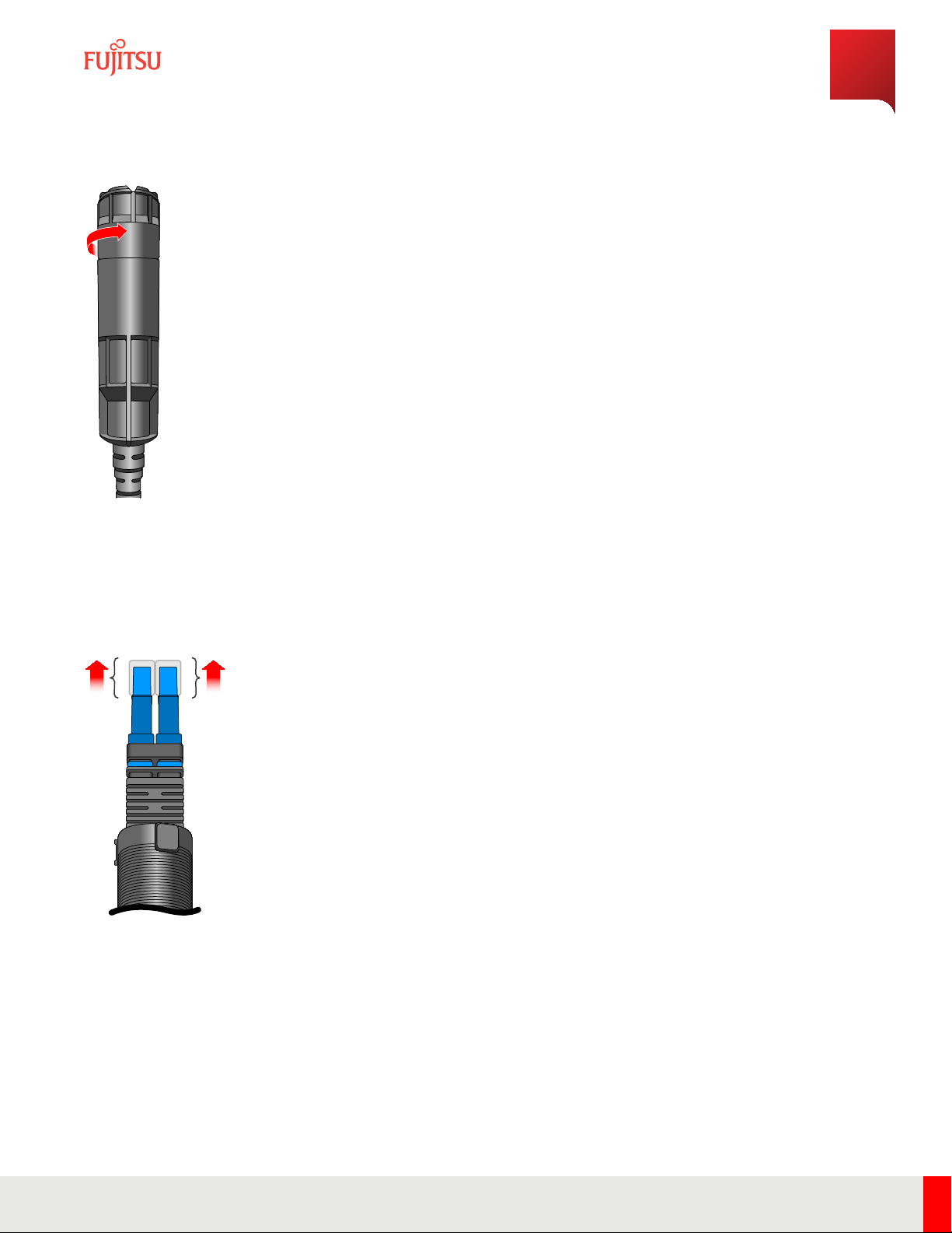
Pull back on the ber enclosure until the cylindrical cable container is completely visible.
Step 7
Clean the optical ber connections.
Installation
Cable Installation
117
Release 1.0 · Issue 1.1, May 2021 Fujitsu and Fujitsu Customer Use Only
Note: For more information about cleaning optical connectors, refer to LC End Surface Cleaning and End Surface
Cleaning In LC.
Step 8
Insert the optical cables into the SFP that is pre-positioned in the connector of the RU.
FNC001640_Rev_01
Figure 35
Insert Optical Fiber
Step 9
Ensure the locking latches of the LC ber connectors are snapped into position.
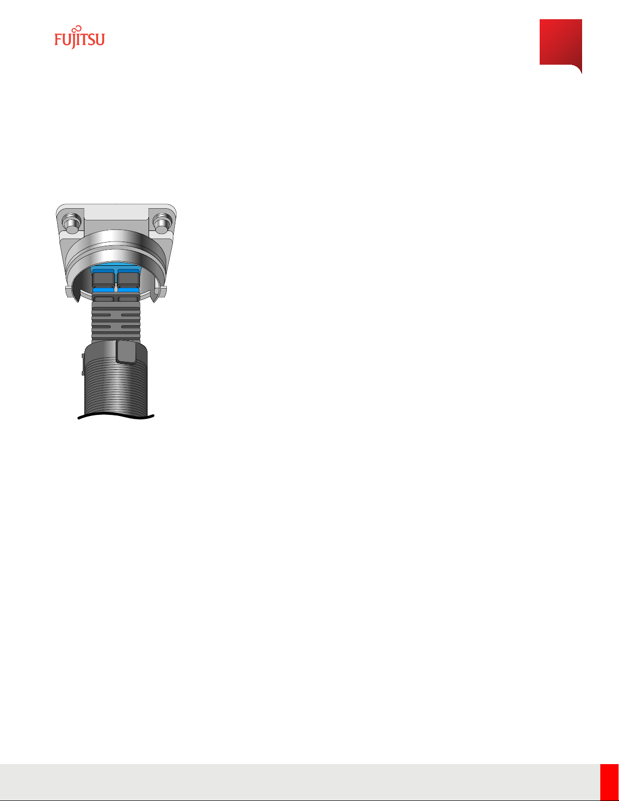
Step 10
Align the connector key on connector to the connector on the RU and insert the connector.
Installation
Cable Installation
118
Release 1.0 · Issue 1.1, May 2021 Fujitsu and Fujitsu Customer Use Only

FNC001645_Rev_01
Figure 36
Align Connector
Step 11
Insert the cable and turn the enclosure sub-assembly clockwise until it clicks into place.
FNC001638_Rev_01
Figure 37
Insert Connector
Installation
Cable Installation
119
Release 1.0 · Issue 1.1, May 2021 Fujitsu and Fujitsu Customer Use Only

FNC001641_Rev_01
Figure 38
Secure Enclosure
Step 12
Mate the two protective covers together to keep the covers intact and clean.
Step 13
Apply weatherproong to the SFP cable connector per local guidelines to protect from moisture intrusion.
Note: Fujitsu recommends using industry standard UL approved self-fusing tape, but users may use any UL
approved weatherproong material. Refer to Weatherproong RU Connections for more information about
weatherproong methods.
Continue with the next task.
4.6.3
Connect AISG Cables
is procedure describes how to connect AISG cables to the RU.
Prerequisites:
■RU mounted and not powered up
■Available AISG cables
■Weatherproong method to prevent moisture intrusion
Step 1
Remove the protective cover from the RET port.
Installation
Cable Installation
120
Release 1.0 · Issue 1.1, May 2021 Fujitsu and Fujitsu Customer Use Only

FNC001719_Rev_01
Figure 39
RET Port Location
Step 2
Install the AISG cable to the RET port on the boom of the RU.
Step 3
Route the cable to the respective port on the antenna.
Step 4
Connect the AISG cable to the RET port on the antenna and tighten until rm.
Step 5
Tighten the outer connector shell to secure the cable. Repeat for the antenna end of the cable.
Step 6
Apply weatherproong to the AISG cable connector per local guidelines to prevent moisture intrusion.
Note: Fujitsu recommends using industry standard UL approved self-fusing tape, but users may use any UL
approved weatherproong material. Refer to Weatherproong RU Connections for more information about
weatherproong methods.
Continue with the next task.
4.6.4
Connect RF Cables
is procedure describes how to connect RF cables to the RU.
Installation
Cable Installation
121
Release 1.0 · Issue 1.1, May 2021 Fujitsu and Fujitsu Customer Use Only
Table of contents
Other Fujitsu Cables And Connectors manuals


