Fracarro 3DG-2S2-2T User manual
3DG-2S2-2T
Operating instructions

2
English
• Theproductcanonlybeinstalledbyqualiedpersonnelincompliancewithlocalsafety
lawsandregulations.FracarroRadioindustrieisfreefromallcivilandcriminalresponsibility
duetobreachesofthecurrentlegislationderivedfromtheimproperuseoftheproductby
theinstaller,userorthirdparties.
• Theproduct must beused infull compliancewith theinstructions givenin thismanual,
in order to protect the operator against all possible injury and the product from being
damaged.
Installation warnings
• Theproductmustnotbeexposedtowaterdripsandmustbeinstalledindoorsinsidein
dryplaces.
• Dampandcondensationdropscoulddamagetheproduct.Consequentlyalwayswaitfor
theproducttobeperfectlydrybeforeuse.
• Donotinstalltheproductaboveorclosetosourcesofheat,industyatmospheresorwhen
itcouldbeexposedtocorrosivesubstances.
• Hightemperaturesoroverheatingcouldcompromisetheproductfunctionsandlife.
• Handlewithcare.Knockscoulddamagetheproduct.
• Leaveplentyofspacearoundtheproducttoensuresufcientventilation.
• Ifyouwall-mounttheproduct,useexpansionanchorsthataresuitableforthecharacteristics
ofthesupportbracket.
Earthing the antenna
• Theproductmustbeconnectedtotheantennalineearthelectrodeincompliancewiththe
EN60728-11standard.
• Theearthscrewisindicatedwiththesymbol
• ItisimportanttoobservethedispositionsoftheEN60728-11standardandnotconnectthis
screw(terminal)(product)tothepowersupplyearthline.
IMPORTANT
• Never remove the product cover: dangerous powered components could be accessible
whenthecasingisopened.
• Incaseofamalfunction,donotattempttorepairtheproductbecausethiswouldinvalidate
theguarantee.
1. SAFETY WARNINGS

3
English
Operating instructions
The 3DGex unit has a cabinet for housing up to a maximum of 6
differenttypesofmoduleandacontrolunitthathasvariousfunctions.
Thecontrolunitintherstslotenables:
• Poweringupto6cards
• Programmingtheunitusingthekeypadandon-boarddisplay.
• Programmingtheentirecentralstationlocallyorremotelyusingthe
LANportandthewebinterface
• Monitoring the central station locally or remotely using the LAN
port, and to receive the signals via email in case of problems
(CONTROLLERHOSTincluded)
• Importingandexportingcongurationstoandfromotherstationsof
thesametypebymeansoftheUSBportorthePCmemory
• Visuallycheckingthestationstatus,bymeansofthetwosignalleds
Thecabinetdoesnotjustphysicallyhousethemodulesbutalso:
• Enablestransferringthecorrectvoltagetothemodules.
• Enablescommunicationsbetweenthemodulesandcontrolunitfor
programmingandremotemonitoring.
• Enablescarryingforwardthetunedinsignalsfromothermodules,
usingitasanadditionalinputonthebackpanel.
• MixestheoutgoingRFsignalsandampliesthem.
ThecabinetalsoprotectstheaccesstotheconnectionsandCAMS,
owingtoadoorwithlockandkeyandaprotectiveshellfortheCAMs.
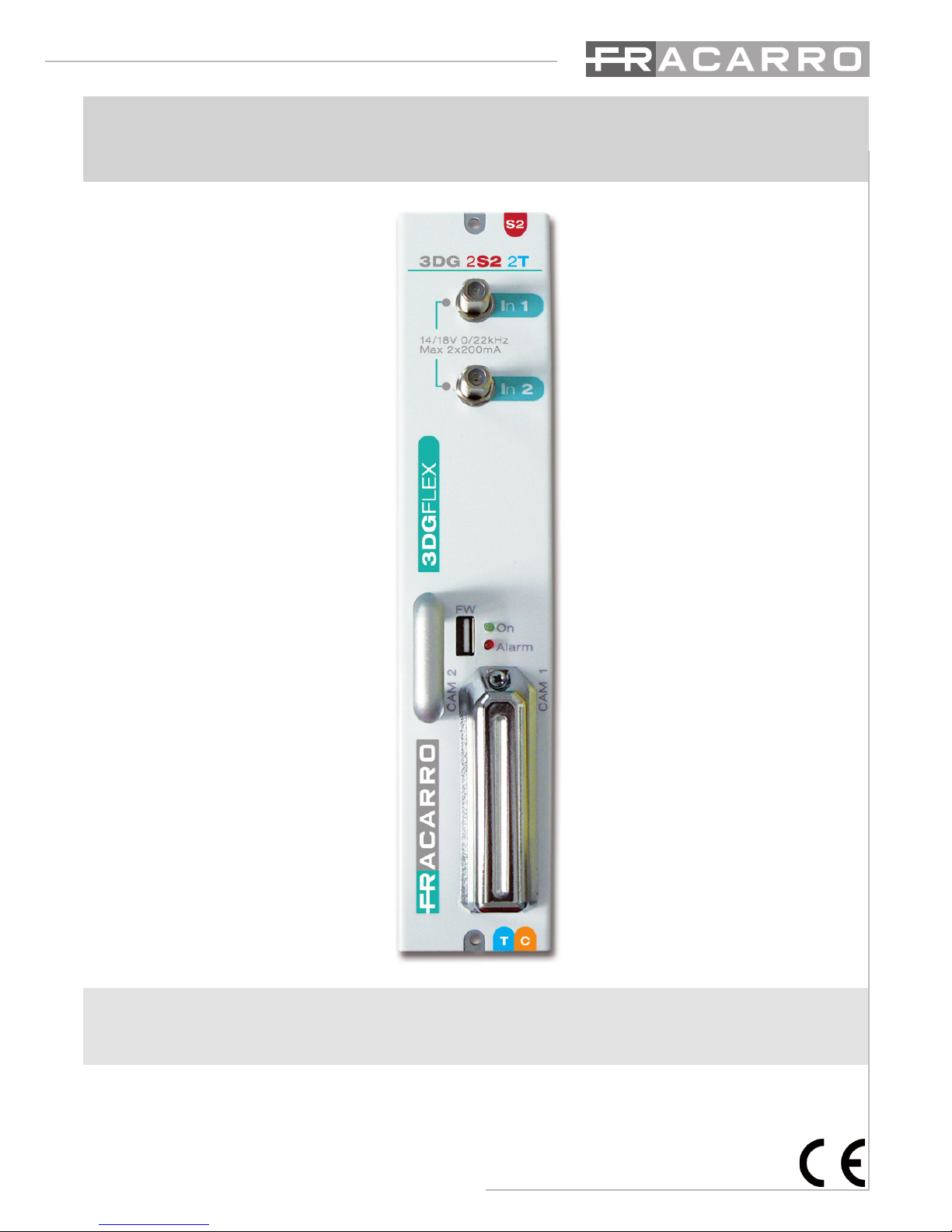
The 3DG-2T2-2T module can be housed in the 3DGFlex unit, and
enablescreating2channelsinDVB-TorDVB-Cstandard,beginning
fromthestreamof1,2or3satellitetransponders(QPSK-DVB-S2).
Infact,2DVB-TorDVB-Cmuxescanbecreatedusingassourcesthe
contentsof2differentsatellitetransponders,comingfrom2inputs,
andathirdsatellitetransponderwiththetrasportstreamthoughthe
backpanelcominginasinputfromapreviousmodule.
Themodulatorisfullband,thereforethe2muxescanbemodulatedon2VHF-UHFband
channels.
Eachmodule has2 satelliteinputs (SAT 1e SAT 2)and adouble commoninterface slot
associated to each of the 2 inputs, which enables decrypting programs from the same
transportstream.
ThereisalsoaUSBportforrapidlyupdatingthermwaredirectlyfromtheUSBdrive,and
forcopyingthemodulecongurationparameterstoorfromthedriveusingthecontrolunit
USBport.
Itcanbeprogrammedinoneoftwoways:Basicmoduleprogrammingusingthekeypadand
LCDdisplayonthestationcontrolunit;completeprogrammingusingthewebinterfacewith
alocalorremotePCconnectedtotheLANportonthecontrolunit.
Each3DG-2S2-2Tcangenerate14/18Vperinput,22KHztoneandDISEqC1.0tone-burst
tocontrolothermultiswitches,ifany,orLNBandisequippedwithashort-circuitprotection
device.Max.remotepowermaximumcurrent200mA@14V/18Vperinput.
2. PRODUCT DESCRIPTION
Importingandexportingcongurationstoandfromotherstationsof

4
English
CAMinsertion ToremovetheCAM,press
thecorrespondingbutton
3. PRODUCT INSTALLATION
3.1 PACKAGING CONTENTS
All’internodell’imballosonocontenutiiseguentimateriali:
• modulo3DG
• avvertenzeperlasicurezzael’installazionedelprodotto
3.2 MODULE ASSEMBLY
3.3 INSERTION AND REMOVAL OF THE CAM MODULES
Seethegures:

5
English
Operating instructions
1.Insertthemoduleintotheheadend(theheadendmustbeoff).
2.SwitchtheheadendON;waitfortheheadendinitialization(theFracarrologoisdisplayed)
3.Connecttheantennacablestotherelevantinputs
4.PresstheVkeyandenterthemenu;entertheuser’scode(1234bydefault)andpressVagain.
Nowtheheadendwill scan andndthe presentmodules.Nowyoucan programtheunitas
speciedfromthepage7.
5.Checktheoutputsignalattheoutputconnectoroftheheadendwithaeldmeter
6.ConnectthedistributioncabletotheTVoutputconnector.
Inalternativaalpunto4èpossibileutilizzareunPCperaccedereallaprogrammazionedelmo-
dulotramiteinterfacciaweb.
Alternativelytoitem4,youcanuseaPCtoprogramthemodulebywebinterface.
Themodulecanberesettodefaultparameters(seethecontrolunit’sinstructions).ATTEN-
TION:thedefaultlanguageisEnglish.
Afterresetting,youcansettheparametersagainasdefaultparametersmightnotmeetyour
needs.
The3DG-2S2-2TunitisequippedwithtwofrontLEDs(redandgreen)whichindicatethemo-
dulestatus(i.e.ON,underalarm,underlockage,underbootingorprogramming).
Thefollowingtablehelpsunderstandtheluminoussignalizations.
LED STATUS – START UP
GREEN LED RED LED MEANING
ON ON Systemstartup
FLASHING OFF Applicationstartup
ON OFF Systemready
LED STATUS – SYSTEM READY
GREEN LED MEANING
ON Normaloperation
FLASHING Systemcommunicatingviaweborkeyboard
RED LED MEANING
OFF Normaloperation
ON Faultand/oroverow
FLASHING Inputenabledwithoutsignal
BOOTING STATUS
GREEN LED RED LED MEANING
OFF Flashing Updatingand/orrecoveryphase
4. INSTRUCTIONS FOR USE

6
English
5. PROGRAMMING INSTRUCTIONS
NB:TheControlunittimeoutis5minutes:afterthattime,ifnootherchangesaremade,the
controlunitreinstatesthelastsavedmoduleconguration.
5.1 BASE PROGRAMMING FROM THE STATION
The 3DG-2S2-2T module can be programmed using the keyboard on the station control
unit.
To access the programming menu, press √ and input the user code (default is 1234). To
changethe3DG-2S2-2Tlanguageenterthemainmenuinthecontrolunit“LANGUAGE”,
andselecttherequiredlanguagepressing√.
Foralltheprogrammingactivitiesandtounderstandtheprogrammingmenusgiveninthe
followingowcharts,refertothekeygivenbelow:
KEYBOARD KEY FUNCTION
or Forconrminganenteredvalueorenteringthemenu/submenu
or Fordeletinganenteredvalueorexitingthemenu
Fornavigatingamongthevariousitemsofthemenu
Forchangingtheparameters
Forenteringthevalues
Forsavingthechanges
S
...... 9
WXYZ
0
➤
➤
➤
➤
✗
➤
✓➤
➤
➤

7
English
Operating instructions

8
English
Key:
■ OnlyformodulecongurationinDVB-T
■OnlyformodulecongurationinDVB-C

9
English
Operating instructions
Key:
■ OnlyformodulecongurationinDVB-T
■OnlyformodulecongurationinDVB-C

10
English
INPUT
Set frequency (SAT 1):
DiSEqC:allowssettingtheDiSEqCaccordingtothesatellite(A,B,CoD).
FREQ.(MHz):allowssettingtheextendedfrequencyforthetranspondertobereceived.
POLARITY:tosethorizontalorverticalpolarity.
TYPELNB:tosetthetypeofLNB.
SYMBOLRATE:allowssettingthesymbolrateforthetranspondertobereceived.
Set IF frequency (SAT 1):
DiSEqC:allowssettingtheDiSEqCaccordingtothesatellite(A,B,CoD)
FREQ.IF(MHz):allowssettingtheIFfrequencyforthetranspondertobereceived.
LNB:tosetthetypeofLNB.
SYMBOLRATE:allowssettingthesymbolrateforthetranspondertobereceived.
Measures (SAT 1)
Lock:tocheckwhetherthereceiverhaslockedthesignalornot.
Networkname:-readingonly–tocheckthetranspondername.
BER:toviewtheBER(quality)oftheinputsignal.
SNR:toviewthesignal/interferenceratiooftheinputsignal.
Common Interface (SAT 1)
Modulename:toverifythecommoninterfacemodulename.
Enabledprograms:toaddorremovetheprogramstobedecrypted.
ResetCAM:toresettheCAM
SAT 2= see SAT 1
BACK PANEL
Enable:
OFF:deactivatestheTPinputsignalfromthebackpanel
ON:enablestheTPinputsignalfromthebackpanel
OUTPUT
(mux 1)
Configuration:
Output frequency:
Bandwidth(onlyformodulessetinDVB-T):tosettheoutputchannelbandwidth
fromtheavailableones(6,7,8MHz)
Frequency(MHz):tosettheinputchannelfrequency
Output channel:
Country:tosettheinstallationcountrychannels.
Outputchannel:tosettheoutputchannel.
Table of contents
Other Fracarro Control Unit manuals


Popular Control Unit manuals by other brands

Festo
Festo Compact Performance CP-FB6-E Brief description

Elo TouchSystems
Elo TouchSystems DMS-SA19P-EXTME Quick installation guide

JS Automation
JS Automation MPC3034A user manual

JAUDT
JAUDT SW GII 6406 Series Translation of the original operating instructions

Spektrum
Spektrum Air Module System manual

BOC Edwards
BOC Edwards Q Series instruction manual

KHADAS
KHADAS BT Magic quick start

Etherma
Etherma eNEXHO-IL Assembly and operating instructions

PMFoundations
PMFoundations Attenuverter Assembly guide

GEA
GEA VARIVENT Operating instruction

Walther Systemtechnik
Walther Systemtechnik VMS-05 Assembly instructions

Altronix
Altronix LINQ8PD Installation and programming manual


