Fluke 707 User manual
English Instruction SheetPanel 1
®
707
Loop Calibrator
Instruction Sheet
Introduction
The Fluke 707 Loop Calibrator (hereafter, the Calibrator) is a
compact sourcing and measuring tool. The Calibrator tests current
loops of 0-20 mA or 4-20 mA and measures dc voltage to 28 V. It
comes with a set of alligator-clip test leads, a 9 V alkaline battery,
and this Instruction Sheet.
The Calibrator is a IEC 61010, CAT I 30 V, Pollution Degree 2
instrument. A CAT I instrument is designed to protect against
transients from high-voltage, low-energy sources, like electronic
circuits or a copy machine, for example.
Calibrator Capabilities
Function Range Resolution
Measure V dc 28 V 1 mV
Measure mA dc
Source mA dc 0 to 24 mA 1 μA
Source loop power 24 V dc N/A
Battery Saver
The Calibrator automatically turns off after 30 minutes of inactivity.
To reduce this time or disable this feature:
1. With the Calibrator OFF, press D.
PSXX is displayed, where XX is the turn-off time in minutes.
OFF means the power saver is disabled.
2. Turn mto decrease or increase the turn-off time.
To disable, turn muntil the display shows OFF.
3. The Calibrator resumes normal operation after 2 seconds.
August 2001 (English) Rev. 2, 2/08
© 2001-2008 Fluke Corporation. Product specifications are subject to
change without notice. All rights reserved.
English Instruction SheetPanel 2
WWarnings and Cautions
To avoid electric shock, injury, or damage to the
Calibrator:
•Use the Calibrator only as described in this
Instruction Sheet or the protection provided by the
Calibrator may be impaired.
•Do not use the Calibrator around explosive gas,
vapor, or dust.
•Inspect the Calibrator before use. Do not use it if
appears damaged.
•Check the test leads for continuity, damaged
insulation, or exposed metal. Replace damaged
test leads.
•Never apply more than 30 V between any two
terminals, or between any terminal and earth
ground.
•Use the proper terminals, mode, and range for your
measuring or sourcing application.
•To prevent damage to the unit under test, put the
Calibrator in the correct mode before connecting
the test leads.
•When making connections, connect the COM test
lead before the live lead; when disconnecting,
disconnect the live lead before the COM lead.
•Never use the Calibrator with the case open.
•Make sure the battery door is closed before you
use the Calibrator.
•Replace the battery as soon as the M(low battery)
symbol appears to avoid false readings that can
lead to electric shock.
•Remove test leads from the Calibrator before
opening the case or battery door.
Symbols
Symbol Meaning
+ON / OFF button.
JEarth ground
WCaution: Important information. Refer to instruction sheet
hCaution: Static discharge can damage parts
TDouble insulated
MBattery
)Conforms to relevant Canadian Standards Association
directives. Certification # LR110460-2.
PConforms to European Union requirements
FDirect current
~Do not dispose of this product as unsorted municipal
waste. Go to Fluke’s web site for recycling information.

English Instruction SheetPanel 3
Pushbutton Functions
Pushbutton Function
DON or OFF button.
A+ D
(Power-on Option)
Press Aand Dsimultaneously to toggle
between the mA output spans.
•4 mA to 20 mA = 0 % - 100 % (default)
•0 mA to 20 mA = 0 % - 100 % (optional)
The selection is saved until it is changed.
l+ D
(Power-on Option)
Press l+ Dsimultaneously to turn HART
resistor (Hr) on. Default is off.
APress to step through modes:
•Source mA
•Simulate mA
•Measure mA
•Loop Power (24 V)
•Measure V dc
hij
Turn nto increase or decrease current output.
Current output can be adjusted at a resolution of
1 μA or 100 μA. (Default is 1 μA.)
•To adjust the current in 1 μA steps, simply
turn the knob.
•To adjust the current in 100 μA steps, press
in and turn the knob.
BPress Bto step the current up 25 % of full
scale (20 mA).
At full scale, press Bto step the current down
25 % of full scale.
B+ CPress B+Csimultaneously to enter the
Auto Ramp mode and select a ramp form.
A continuously applied or controlled mA ramping
signal is produced in one of three ramp forms.
e(slow), g(fast), or f(step) identifies the
selected ramp form.
CPress Cto start the SpanCheck™at 0 % of
selected current span, i.e., 0 mA for 0-20 mA span
or 4 mA for 4-20 mA span.
dis displayed.
Press again for 100 % of selected current span.
English Instruction SheetPanel 4
Using the mA Sourcing (Output) Modes
The Calibrator outputs current for calibrating and testing 0 to 20 mA
and 4 to 20 mA current loops and instruments.
In SOURCE mode, the Calibrator supplies the current.
In SIMULATE mode, the Calibrator simulates a 2-wire transmitter in
an externally-powered current loop.
Changing the mA Output Span
The Calibrator has two mA output spans:
•4 mA to 20 mA (0 % to 100 %) [default]
•0 mA to 20 mA (0 % to 100 %) [optional]
To change the output span, turn the Calibrator off. Press A+ D
simultaneously. The selected setting is saved until it is changed
again.
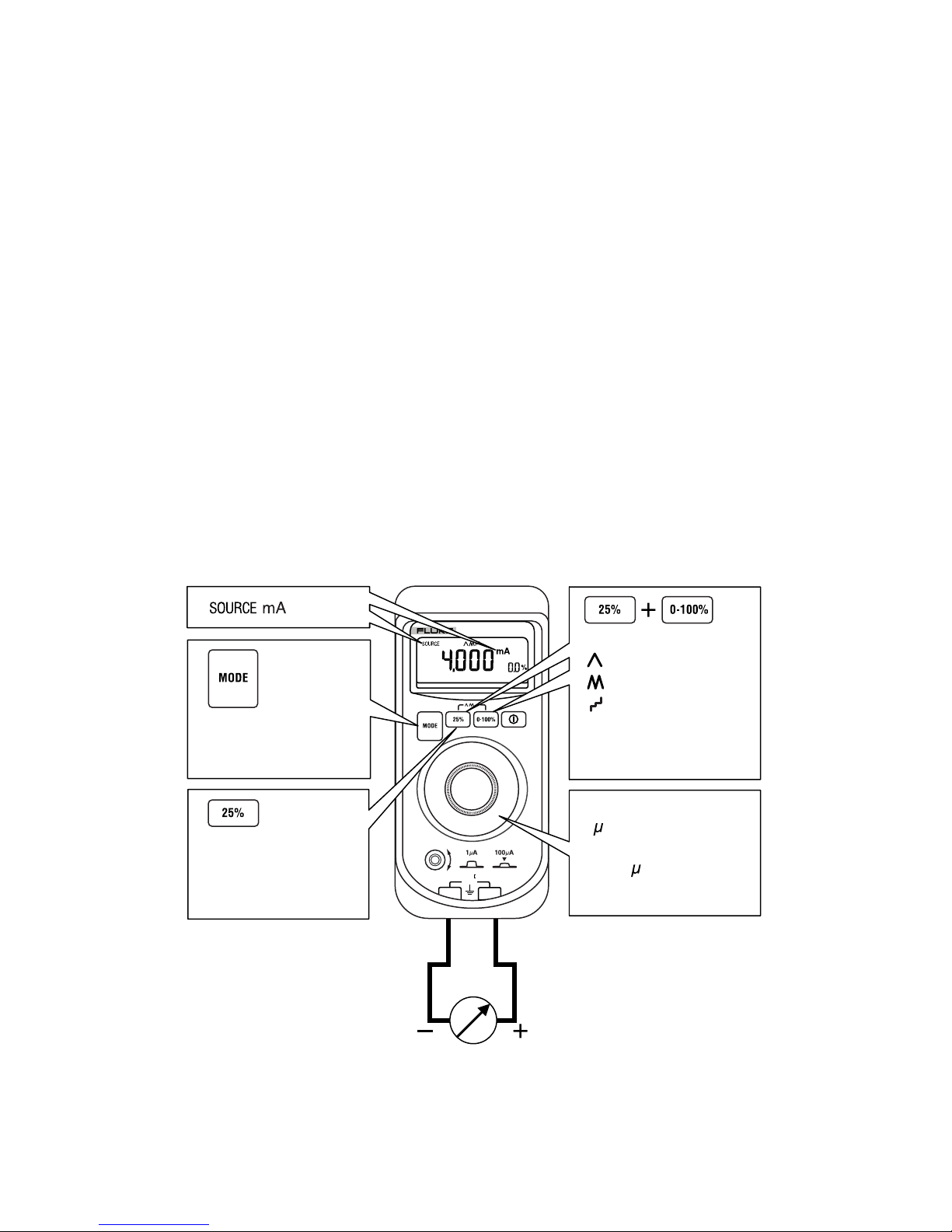
Sourcing mA
Use SOURCE mode to supply current to a passive circuit.
A path must exist for current to flow between the +and COM
terminals. Otherwise the display indicates an overload (OL) when
you set an output value.
COM
+
707
LOOP CALIBRATOR
30V
CAT
Press until SOURCE
mA is displayed.
Press to step current
up/down in 25 %
steps of full scale.
Turn to step up/down
1 A. Press in and
turn to step up/down
in 100 A increments.
Press simultaneously
once for slow ramp
twice for fast ramp
three times for
stepped ramp.
ADA04F.EPS

English Instruction SheetPanel 5
Contacting Fluke
To contact Fluke for product information, operating assistance,
service, or to get the location of the nearest Fluke distributor or
service center, call:
1-888-44-FLUKE (1-888-443-5853) in U.S.A
1-800-36-FLUKE in Canada
+31-402-675-200 in Europe
+81-3-3434-0181 Japan
+65-738-5655 Singapore
+1-425-446-5500 from other countries
Or visit Fluke's web site at: www.fluke.com.
Register your Calibrator at: http://register.fluke.com.
Address correspondence to:
Fluke Corporation Fluke Europe B.V.
P.O. Box 9090, P.O. Box 1186,
Everett, WA 98206-9090 5602 BD Eindhoven
U.S.A. The Netherlands
Limited Warranty & Limitation Of Liability
This Fluke product will be free from defects in material and work-
manship for 3 years from the date of purchase. This warranty
does not cover fuses, disposable batteries, or damage from
accident, neglect, misuse, alteration, contamination, or abnormal
conditions of operation or handling. Resellers are not authorized
to extend any other warranty on Fluke’s behalf. To obtain service
during the warranty period, contact your nearest Fluke authorized
service center to obtain return authorization information, then
send the product to that Service Center with a description of the
problem.
THIS WARRANTY IS YOUR ONLY REMEDY. NO OTHER
WARRANTIES, SUCH AS FITNESS FOR A PARTICULAR
PURPOSE, ARE EXPRESSED OR IMPLIED. FLUKE IS NOT
LIABLE FOR ANY SPECIAL, INDIRECT, INCIDENTAL OR
CONSEQUENTIAL DAMAGES OR LOSSES, ARISING FROM
ANY CAUSE OR THEORY. Since some states or countries do
not allow the exclusion or limitation of an implied warranty or of
incidental or consequential damages, this limitation of liability
may not apply to you.
11/99
English Instruction SheetPanel 6
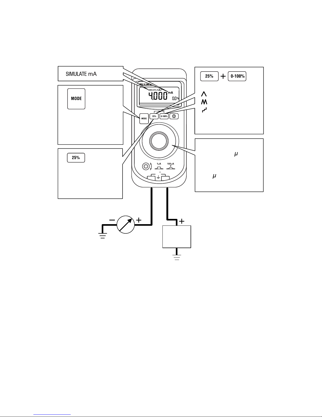
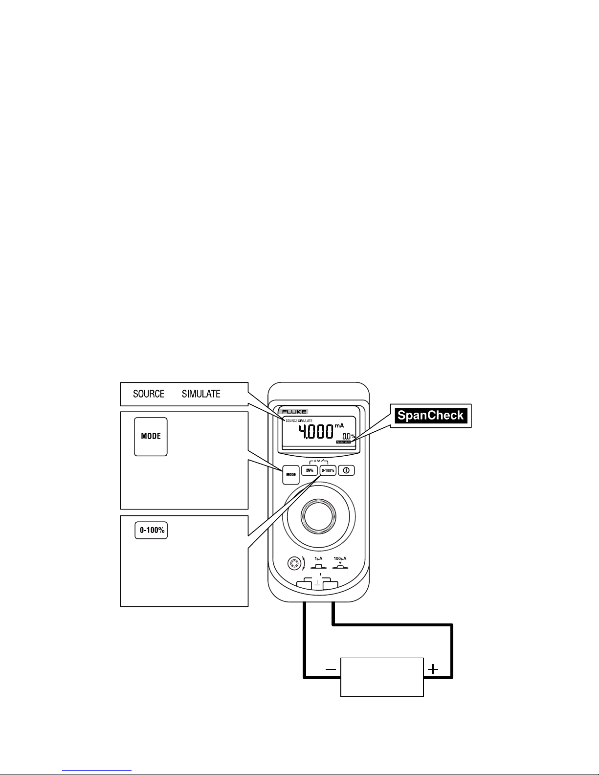
Simulating a Transmitter
When simulating the operation of a transmitter, the Calibrator
regulates the loop current to a known value selected by you.
A 12 V to 28 V loop supply must be available. Insert the test leads as
shown below.
Power
supply
30 V dc
max.
COM
+
707
LOOP CALIBRATOR
30V
CAT
Press until
SIMULATE mA is
displayed.
to step current
up or down 25 %
of full scale.
Press
Turn to step
up/down 0.1 A.
Press in and rotate
to step up/down in
100 A increments.
Press simultaneously
once for slow ramp
twice for fast ramp
three times for
stepped ramp.
ADA05F.EPS
English Instruction SheetPanel 7
Auto Ramping the mA Output
Auto ramping allows you to continuously apply a varying current from
the Calibrator to a passive (sourcing) or active (simulate) loop. Your
hands remain free to test the transmitter’s response.
Press B+ Csimultaneously to enter the Auto Ramp mode and
step to a ramp type.
The Calibrator applies or controls a continuously repeating mA signal
over a 0-20 mA or a 4-20 mA span in one of three ramp types:
Slow (e) 0 % to 100 % to 0 % smooth ramp over 40 sec.
Fast (g) 0 % to 100 % to 0 % smooth ramp over 15 sec.
Step (f) 0 % to 100 % to 0 % stair-step ramp in 25 % steps,
pausing 5 sec at each step.
To exit, press any pushbutton or turn the Calibrator off.
Using the SpanCheck Function
The SpanCheck™ function checks the zero and span points of a
transmitter in either SOURCE or SIMULATE mode.
To select SpanCheck, press C.
To exit, press any pushbutton or turn the knob.
Device under
test
30 V dc max.
COM
+
707
LOOP CALIBRATOR
30V
CAT
Put in SOURCE mA
or SIMULATE mA.
or
Press to start
SpanCheck at 0%.
Press again for 100%.
ADA02F.EPS
English Instruction SheetPanel 8
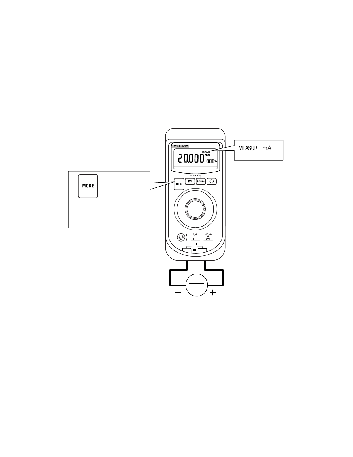
Measuring dc mA
WCaution
To prevent damage to the unit under test, ensure that the
Calibrator is in the correct mode before connecting the
test leads.
To measure dc mA:
1. Press Ato step to MEASURE mode.
MEASURE mA is displayed.
2. Touch test lead probes to the circuit across the load or power
source as shown below.
COM
+
707
LOOP CALIBRATOR
30V
CAT
Press until MEASURE
mA is displayed.
30 V dc max.
ADA03F.EPS
English Instruction SheetPanel 9
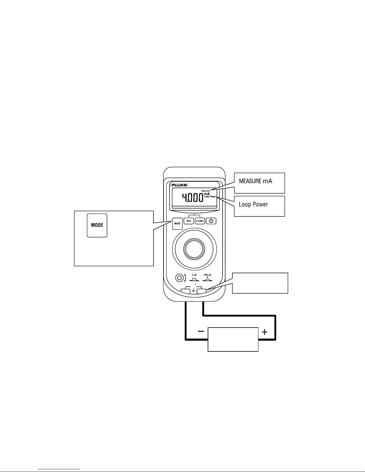
Measuring dc mA with Loop Power
WCaution
To prevent damage to the unit under test, ensure that the
Calibrator is in the correct mode before connecting the
test leads.
Loop power provides +24 V to power a transmitter and to read loop
current simultaneously.
To measure dc mA with Loop Power:
1. Press Ato step to Loop Power mode.
MEASURE mA and Loop Power are displayed.
2. Touch test lead probes to the circuit across the load or power
source as shown below.
To exit Loop Power, change measurement mode.
Two-wire
transmitter
30 V dc max.
COM
+
707
LOOP CALIBRATOR
30V
CAT
Press until Loop
Power is displayed.
+24 V output
ADA06F.EPS
English Instruction SheetPanel 10
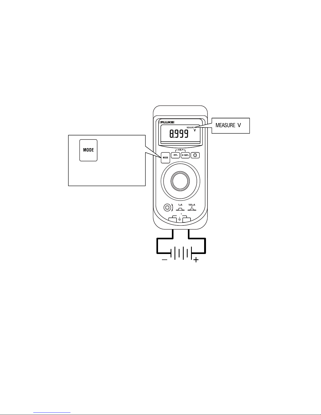
Measuring dc Volts
WCaution
To prevent damage to the unit under test, ensure that the
Calibrator is in the correct mode before connecting the
test leads.
To measure dc Volts:
1. Press Ato step to MEASURE mode.
MEASURE V is displayed.
2. Touch test lead probes across the load or power source.
30 V dc max.
COM
+
707
LOOP CALIBRATOR
30V
CAT
Press until MEASURE
V dc is displayed.
ADA01F.EPS
Other manuals for 707
2
Table of contents
Other Fluke Test Equipment manuals


Fluke
Fluke 709 Use and care manual

Fluke
Fluke 9009 User manual

Fluke
Fluke 729 Pro User manual

Fluke
Fluke T5-600 Operating and installation instructions

Fluke
Fluke TS54 User manual

Fluke
Fluke 190-502/AM Instruction manual

Fluke
Fluke 154 HART User manual

Fluke
Fluke 4180 Quick start guide

Fluke
Fluke 9132A User manual

Fluke
Fluke 9144 User manual


