
FLUENCE SPYDR 2 Series User manual

USER MANUAL
IMPORTANT SAFETY PRECAUTIONS & EXPLANATION OF SYMBOLS . . . . . . . . . . .2
CULTIVATION BEST PRACTICES . . . . . . . . . . . . . . . . . . . . . . . . . . . . . . . . .2
GENERAL CARE . . . . . . . . . . . . . . . . . . . . . . . . . . . . . . . . . . . . . . . . . . 3
SYSTEM HARDWARE & ACCESSORIES . . . . . . . . . . . . . . . . . . . . . . . . . . . . 4
FIXTURE ASSEMBLY INSTRUCTIONS. . . . . . . . . . . . . . . . . . . . . . . . . . . . . .5
FIXTURE MOUNTING INSTRUCTIONS . . . . . . . . . . . . . . . . . . . . . . . . . . . . . 6
CAUTIONS & WARNINGS . . . . . . . . . . . . . . . . . . . . . . . . . . . . . . . . . . . 14
PRODUCT GUARANTEE & WARRANTY. . . . . . . . . . . . . . . . . . . . . . . . . . . . 20
SPYDR 2 Series
2x • 2p • 2i • 2h

2
IMPORTANT SAFETY PRECAUTIONS & EXPLANATION OF SYMBOLS
• Please read this manual thoroughly before attempting to install or
operate any Fluence SPYDR 2 Series system.
• After successful installation and configuration of the system, be sure to
retain this manual in a safe place for future reference. Safety is a key
component to a long lasting and trouble-free installation.
•It is important you read, fully understand, and observe the subsequent
safety precautions. If you are not comfortable with the installation of
high performance lighting systems, you should seek the services of a
qualified installation professional or call us for help.
• NOTICE: The SPYDR 2x, SPYDR 2p, SPYDR 2i and SPYDR 2h are high-
performance lighting systems. Do not touch while in operation.
• Connect the system only to the power sources of the appropriate voltage
using the AC plug type received. Protect power cables from being
pinched, walked on, or otherwise damaged. Be especially careful where
the power cable enters the power outlet and the unit. Only connect the
system to an electrical outlet or extension cord of appropriate type and
rating. Connect the system only to the power sources of the correct
voltage using the plug received.
• DO NOT defeat the safety purpose of a grounding or polarized plug by
removing ground pins or using unsafe adapters. A polarized plug has
two blades –one wider than the other. A grounding plug has a third
ground prong in addition to the two main conductors. The wide blade
or third grounding prong is provided for your safety. If the provided plug
foes not fit your outlet, consult an electrician to replace your obsolete
outlet. If you replace the power cord, only use one of similar type and
equal or greater current rating.
•The system should only be cleaned as directed in the manual. You should
seek service for your system by qualified service personnel if any of the
following occur:
1. The power-supply cord or the plug has been damaged.
2. The unit has been exposed to rain.
3. The unit exhibits a marked change in performance.
4. The unit has been dropped, or its enclosure or chassis is damaged.
CULTIVATION BEST PRACTICES
Fluence encourages everyone to experiment and pursue their own techniques.
Every crop is different and everyone has different goals. However, our internal
research has given us insight into several strategies we would like to share.
•Regularly check your plants’ growth and health. Fluence lighting systems
deliver high levels of PAR, typically more than experienced in nature.
Adjustments to H2O, CO2, RH, nutrients, and temperature are typically required.
• Mount the fixture at least 6” from the top of your canopy to ensure optimal
uniformity and consistent PPFD. The SPYDR Series was designed to provide
uniform light dispersion and requires precise deployment. A 1” variation in
either direction will have a significant change in uniformity and PPFD (which
may or may not be desired).
• Many plants prefer higher temperatures when exposed to high PPFD.
Experiment with higher temperatures to achieve higher yields. Canopy
temperature and room ambient temperature often vary. For accurate results,
test at the canopy level to gauge leaf surface temperature.
For cultivation recommendations visit
www.fluence.science/science-articles/

3
GENERAL CARE
SPYDR 2 system is passively cooled with zero moving components. They are
designed for harsh environments and years of maintenance-free performance.
Some basic care will keep your system operating at peak performance cycle-
after-cycle.
•Natural convection removes heat away from the heatsink. In order for
the system to properly cool itself, at least one inch of space is required
between the console and the roof of your grow area. Failure to do so may
shorten the fixture’s lifespan.
• To achieve the optimal lifespan and performance of your fixtures, routinely
check for and remove excess dust, debris, and mineral build up from
heatsink and LED array. Cleaning should always be done with the fixture
unplugged from its power source using low-pressure compressed air or
water to rinse away dirt from light bars.
• Never use a cloth to clean the diode array. Doing so can scratch or
compromise the integrity of the silicon seal, or dislodge diodes entirely.
• To limit degradation, avoid touching the diodes with your hands, even in a
powered off state.
For detailed instructions for maintenance and cleaning,
please visit www.fluence.science/support-center/.
SPYDR 2 is a high-performance lighting system.
Do not touch while in operation.
PLEASE RECYCLE ALL PACKAGING MATERIAL
4
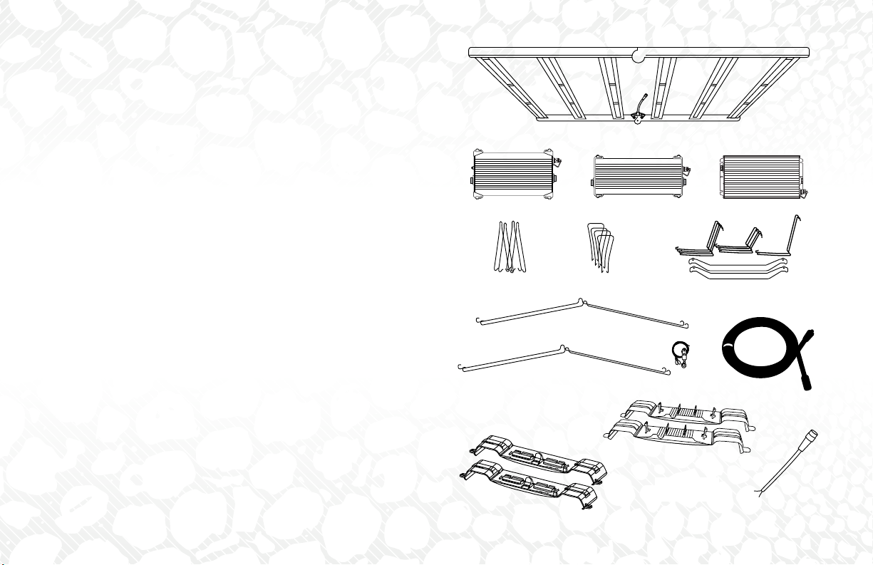
SYSTEM HARDWARE & ACCESSORIES
SYSTEM HARDWARE
ASPYDR 2x, 2p, 2i or 2h light fixture, pre-configured with
A1 Standard DC cable
A1 Standard DC Cable
BPower Supply
B1 600W, Power Supply for SPYDR 2i and 2p
B2 320W, Power Supply for SPYDR2x
B3 800W Power Supply for SPYDR 2h
MOUNTING HARDWARE OPTIONS
(depending on your selection at the time of purchase)
C1 Waterfall Mount
C2 Solid Decking Level or Offset Mount
C3 2-Point Lance Hanger
C4 Adjustable Hanging Kit
C5 ABS/Flood Tray with/without VAS
ACCESSORIES
D Power Supply Accessories
D1 (1) 3’ or 6’ DC extension cable (sold separately)
D2 (2) 800W power supply mounting brackets (to 2h light fixture)
D3 (2) 600W/320W power supply mounting brackets
(to 2x, 2p, and 2i light fixture)
D4 (1) Pigtail Dimming Adapter (sold separately)
D5 (1) AC Power Cord, 6’ (1.83m) or 15’ (4.57m) if ordered with
product (Not shown)
A
B
B1 B2 B3
A1
C1 C2
C3
C4
C5
D1
D2
D3
D4

5
FIXTURE ASSEMBLY INSTRUCTIONS
Take caution when handling light bars. Ensure the LED
array does not come in contact with sharp objects or
force that may damage the diodes.
Unbox and unfold light bar module.
Place on flush, stable surface. Make sure LEDs are facing down.
Install power supply brackets to power supply and then to light bar
module.
DO NOT push directly on power supply to attach to the
two center light bars. Use the clips on the corner of the
bracket to the two center light bars.
SPYDR 2x, 2p, and 2i models
i. Place the PSU on a flat level surface and identify the reinforced
corner mounts on unit and securing posts on brackets.
ii. Insert bracket posts into the corner mounts of the PSU. The
center fins of the bracket will fit inside of the PSU’s heat sink.
iii. Push/slide bracket in towards PSU until the bracket clips into
place. Repeat on opposite side.
iv. Once brackets are securely attached flip unit over and clip on to
the two center bars in the middle of the SPYDR2 fixture by using the
clips on the corner of the bracket.
1
2
“CLICK”
“CLICK”
“CLICK”
iii.
i. ii.
iv.
3

6
SPYDR 2 Series fixtures ship with your choice of hanging hardware. To mount your SPYDR 2 fixture, start by identifying a suitable support structure to hang
your fixture from. Common support structures include pallet racks, rolling tables, Unistrut, trusses, and structural channel. For optimal results, two people are
recommended to mount the fixtures.
POWER SUPPLY MOUNTING CONTINUED
SPYDR 2h models
i. Place the PSU on a flat level surface.
ii. Push/slide brackets on to the PSU base flange until you hear a click.
iii. Once brackets are securely attached flip unit over and clip on to
center light bars in the middle of the SPYDR 2h fixture by using the clips
on the corner of the bracket.
NOTE: If there is a need to remove power supply bracket, use tab on
bracket by pulling it up to release from heat sink light bar.
Waterfall
Mount
Solid Decking
Mount Lance Hanger
FIXTURE MOUNTING INSTRUCTIONS
“CLICK”
“CLICK”
iii.
i. ii.
ABS/Flood Tray with/without VAS

7
WATERFALL MOUNTS
Suggested application: Ideal for waterfall (wire) decking on pallet racks or
rolling tables. Hardware included: long or short “V” mounts.
For proper uniformity and flexibility for adjustments, position SPYDR with light
bars perpendicular to the length of the rack.
To mount your SPYDR using waterfall mounts, place SPYDR fixture gently
below the desired hanging area. Identify four points on the waterfall
decking that align with the light bars located second from the end.
NOTE: Hangers to be attached only to the light bars second from
the end.
Loop mounting hardware on the lower wire deck. Installing on the lower
deck allows for slight adjustments when fixture is mounted to ensure
fixture is centered over your canopy.
Once all four brackets are in place, use two people to lift the fixture
up to the mounting hardware. Slightly separate mounting hardware
until the black hooks slide over the light bar to securely grip the bar.
1
2
3
RACK
SUITABLE HANGING LOCATIONS

8
WATERFALL MOUNTS CONTINUED
Adjust SPYDR module to ensure full contact is made on the hooks of
the mounting hardware.
With all four mounting brackets attached to the SPYDR module, you can
adjust the mounting hardware along the waterfall deck or adjust the
SPYDR module along the contact points on the mounting hardware to
center on the 4’ x 4’ area.
SOLID DECKING MOUNTS
Suggested application: ideal for hanging on cross bars in a rack system
with solid decking. Offset version available with drip/flood trays. Hardware
included: Solid decking mounts.
For proper uniformity and flexibility for adjustments, position SPYDR with light
bars parallel to the length of the rack.
To mount your SPYDR using solid decking mounts, place SPYDR fixture
gently below the desired hanging area. Adjust cross bars approximately
2.5 ft – 3 ft along the rack, roughly five inches from the edge of the
SPYDR module.
4
1
5
RACK

9
SOLID DECKING MOUNTS CONTINUED
Left decking to loop each mount on the cross bar, positioned above light
bar located second from the end.
NOTE: do not attach mounting hardware to the end light bars.
Once all four brackets are in place, use two people to lift the fixture up to
the mounting hardware. Slightly separate mounting hardware until the
black hooks slide over the light bar to securely grip the bar.
Adjust SPYDR module to ensure full contact is made on the hooks of the
mounting hardware.
With all four mounting brackets attached to the SPYDR module, you can
adjust the mounting hardware along the cross bar or adjust the SPYDR
module along the contact points on the mounting hardware to center on
the 4’ x 4’ area.
2
3
4
5

10
LANCE HANGERS AND ADJUSTABLE KIT
Suggested application: Ideal for two-point hanging from areas with high
clearance, such as ceilings or other support structures. Hardware included: 2
lance hangers (and adjustable Gripple kit if upgraded at the time of purchase).
Before you mount the SPYDR module, complete the steps to attach the power
supply to the light bars as outlined in the User Guide. PLEASE NOTE: The
power Supply Enclosure MUST be mounted on the center two light
bars before hanging with the Lance Hanger.
To mount your SPYDR using the lance hangers, place SPYDR fixture gently
below the desired hanging area. Identify two points on the structure that
align with center hinges on the SPYDR module.
Hang either the adjustable Hanger kit (if upgraded at time of purchase)
or desired hanging hardware to the support structure, above the center
hinges. If using the Adjustable Hanger Kit, first loop the two cables
around the support structure and thread the straight end through the
fixed loop. Then thread each straight end through the Gripple hook and
pull it up the cable.
On the inside of the SPYDR module there are four lancet openings. The
lance hanger will slide into the inside-two lancet openings. Place lance
hanger under opening, and gently pull the hanger up from the center of
the hanger until the loops snap into place.
1
2
3
This manual suits for next models
4
Table of contents
Other FLUENCE Lighting Equipment manuals




Popular Lighting Equipment manuals by other brands


Qazqa
Qazqa Suplux SL 3 Black 103062 instruction manual

Commercial Electric
Commercial Electric 54568141 Use and care guide

CREE LIGHTING
CREE LIGHTING 304 Series installation instructions

Goobay
Goobay 49867 user manual

ECOMAN ITALIA
ECOMAN ITALIA LED T8 instruction manual

Alkalite
Alkalite Krypton KT-81 user manual


